- Thread starter
- #361
Builder 2010
Staff Sergeant
Thank you!
Assembly is beginning. I started by finishing up the duck unders with gluing in the rails and adding the ladders. It required a bit of dark red touch up.

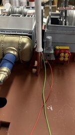
Then big stuff building started with the main condenser. It has to go in first. I can't install the entire unit due to the interference created by the oppositely-facing intake and discharge mains. I chose to epoxy the intake side due to it's complexity and glue the discharge side after the unit is in the ship. The joint isn't so hot due to warpage in the print. I filled it as good as I could.
I then had to epoxy the main supports under it. The first attempt needed a redo when one side had slipped forward before fully curing (5 minute epoxy). I held it in place with a big gravity clamp.

I put all the necessary main propulsion pieces on the ship that required alignment. I found that I couldn't twist the 3º rotation needed by the No. 2 prop shaft.

The reason was insufficient clearance in the holes receiving the piping. With some careful surgery I opened both inlet and discharge openings to give more mobility to the condenser.

It's still not perfect, but better. If I rotate any more the valve wheel on the discharge gate valve sticks out beyond the imaginary bulkhead line. I can rotate the LP turbine itself to align it.
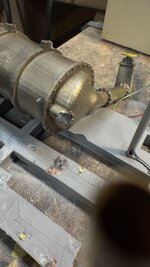
There is one more piece of large framing that surrounds the main gear box; the angle braces at the aftmost gear box wall. I was worried that this piece would need some "doctoring" for the same reason as the other part of the frame due to inpingement with the added vertical bracing that I built. It did need some strategic trimming. I found it best glue this piece directly onto the gear box and not the ship floor. I did this. It took two tries when it broke loose during a trial fit. The failure was gluing to paint and not the substrate. I removed the old CA, sanded the mating surfaces and re-glued.
This view shows this part in place. It's just as hard to view on the real ship as it is in the model.

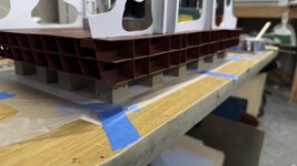
Another trial fit of the startboard lower floor unit showed it's not nestling tight enough and was hanging out over the edge. The cure will be to open the slots around the angle braces more so it cane slide in further.

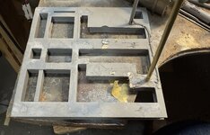
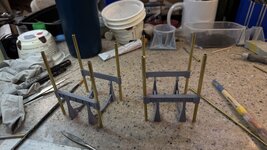
Just when I was thinking about gluing down the main condenser, my brain worked again and realized that I need to fasten all the faux concrete dry dock supports before adding anything to the model. This is for several reasons including not being able to easily invert the model with components added. I also have to figure out the wiring runs vis-a-vis these blocks.
While lying in bed in my "create-while-awakening" period, I came up with a workable plan to attach the block by making a template of the bottom laying out where all the conduits are. Taping the template down and coving with Press-n-Seal food storage film; also taped down. Stick the blocks to the film in their correct locations regarding the conduits and then apply adhesive to all of them and bring the model down on top. I'm still thinking about what kind of adhesive. Of course I can use epoxy since it's longer cure time is a benefit. The other choices would be the 3M Transfer Tape or Servo Foam Tape. Both are pressure sensitive and positioning would have to be correct from the get go. Epoxy would be more forgiving. Any thoughts? I have found that both servo tape and the transfer tape can let go after a whlle, in this use there will be no sheer loads.
On another topic, I got tired of little plastic measuring cups tipping over and spilling. I designed and printed a cup holder. I'm going to make it available on Cults3D as printable .STL files. I tried it yesterday and it worked perfectly. Version 2.0 is being printed today and slimmed down the angle braces and added some finger grooves around the perimeter to facilitate lifting out the cup. I'm printing at least three for myself. I had one cup with paint and the other with CA Accelerator. Since I only had one, the accelerator was sitting on the bench and, of course, I knocked over.


Version 2.0

Assembly is beginning. I started by finishing up the duck unders with gluing in the rails and adding the ladders. It required a bit of dark red touch up.
Then big stuff building started with the main condenser. It has to go in first. I can't install the entire unit due to the interference created by the oppositely-facing intake and discharge mains. I chose to epoxy the intake side due to it's complexity and glue the discharge side after the unit is in the ship. The joint isn't so hot due to warpage in the print. I filled it as good as I could.
I then had to epoxy the main supports under it. The first attempt needed a redo when one side had slipped forward before fully curing (5 minute epoxy). I held it in place with a big gravity clamp.
I put all the necessary main propulsion pieces on the ship that required alignment. I found that I couldn't twist the 3º rotation needed by the No. 2 prop shaft.
The reason was insufficient clearance in the holes receiving the piping. With some careful surgery I opened both inlet and discharge openings to give more mobility to the condenser.
It's still not perfect, but better. If I rotate any more the valve wheel on the discharge gate valve sticks out beyond the imaginary bulkhead line. I can rotate the LP turbine itself to align it.
There is one more piece of large framing that surrounds the main gear box; the angle braces at the aftmost gear box wall. I was worried that this piece would need some "doctoring" for the same reason as the other part of the frame due to inpingement with the added vertical bracing that I built. It did need some strategic trimming. I found it best glue this piece directly onto the gear box and not the ship floor. I did this. It took two tries when it broke loose during a trial fit. The failure was gluing to paint and not the substrate. I removed the old CA, sanded the mating surfaces and re-glued.
This view shows this part in place. It's just as hard to view on the real ship as it is in the model.
Another trial fit of the startboard lower floor unit showed it's not nestling tight enough and was hanging out over the edge. The cure will be to open the slots around the angle braces more so it cane slide in further.
Just when I was thinking about gluing down the main condenser, my brain worked again and realized that I need to fasten all the faux concrete dry dock supports before adding anything to the model. This is for several reasons including not being able to easily invert the model with components added. I also have to figure out the wiring runs vis-a-vis these blocks.
While lying in bed in my "create-while-awakening" period, I came up with a workable plan to attach the block by making a template of the bottom laying out where all the conduits are. Taping the template down and coving with Press-n-Seal food storage film; also taped down. Stick the blocks to the film in their correct locations regarding the conduits and then apply adhesive to all of them and bring the model down on top. I'm still thinking about what kind of adhesive. Of course I can use epoxy since it's longer cure time is a benefit. The other choices would be the 3M Transfer Tape or Servo Foam Tape. Both are pressure sensitive and positioning would have to be correct from the get go. Epoxy would be more forgiving. Any thoughts? I have found that both servo tape and the transfer tape can let go after a whlle, in this use there will be no sheer loads.
On another topic, I got tired of little plastic measuring cups tipping over and spilling. I designed and printed a cup holder. I'm going to make it available on Cults3D as printable .STL files. I tried it yesterday and it worked perfectly. Version 2.0 is being printed today and slimmed down the angle braces and added some finger grooves around the perimeter to facilitate lifting out the cup. I'm printing at least three for myself. I had one cup with paint and the other with CA Accelerator. Since I only had one, the accelerator was sitting on the bench and, of course, I knocked over.
Version 2.0