Allison V-1710 Supercharger Impeller

Ad: This forum contains affiliate links to products on Amazon and eBay. More information in Terms and rules

kool kitty89

Senior Master Sergeant
3,100
101
Aug 29, 2007
San Jose, CA
A while back I discussed the different limitations and qualities of the single stage Merlin (ie 45) and Allison's supercharges. In doing so I saw how much smaller the Allisons supercharger casing apeared, fitted very crampped aganst the back of the engine.

I recently noticed the diameter given for the V-1710's impeller here http://www.raafwarbirds.org.au/targetvraaf/p40_archive/pdfs/1710-33.pdf

At 3.5 inches that would seem unusually small, especially compared to the "cropped" impeller of the low altitude version of the Merlin which was still 9.5" in diameter.

The supercharger seems to have remained the same on the Allison (excluding added auxiliary 2-stage version and turbocharging arrangements) except for the gear ratio. The early versions (with epicyclic reduction gearing) like the V-1710-33 of the P-40/B/C/Tomahawk had an 8.77:1 ratio (8.77x the engine speed) the newer -short nosed- versions (with stronger and simpler spur gearing) had an 8.8:1 rato like the -39,-73 of the P-40E/K (though this may just have been rounded, and the supercharger performance was similar). Additionally there were the 9.6:1 versions like the -81/99 of the P-40N and P-51A which had significantly beter altitude performance. (at the expence of greater charger heating)


The 3.5" figure would seem unusually small, could it be a mistake? (though judging by the engine's dementions and the size of the impeller casing, particularly compared to that of the single stange Merlin's, it would apear to be pretty small)


AllisonV1710-81.jpg


Allison_V-1710_Engine_1.jpg
 
The Standard Impeller diameter was 9.5"

On a few two-speed engines this moved to 10.25"

On the two-stage engines it was 10.25" + 12.18"

I have gear ratios as well if needed.
 
I didn't think there were any single-stage 2-speed versions of the V-1710.

Looking at that page again, it's probably 9 1/2 inches, that portion was hand written and the relolution of the page isn't high enough to make it out completely.


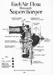
The supercharger casing seems to be much smaller than that of the Merlin's. It seems to lack a vaned diffuser, though maybe it's just the perspective of the photo.
 
Single stage and two speed versions were;

-45
-57
-93
-97
-101
-109
-111
-131
 
Single stage and two speed versions were;

-45
-57
-93
-97
-101
-109
-111
-131

This claim is at odds with info contained in Dan Whitney's book on the Allison. He says that apart from one or two obscure models of the V-1710, two-speed superchargers were not used on this engine.
Perhaps there is confusion here between two-SPEED and two-STAGE supercharger units?
Also, with regard to the original post on this topic, the early versions of the V-1710 had INTERNAL SPUR gear reduction units, not epicyclic.
 
What do you mean by "internal spur" gearing? Epicyclic gearing was also sometimes referred to as planetary spur gearing.

28.jpg


Also, from the above cut-away it looks like the V-1710's supercharger had a vaneless diffuser.
 
Dan Whitney's Vees for Victory is incorrect in this regards. Theres a nice list published by Air Material Command which gives the model designations of USAF engines including details on usage, powers, displacement, supercharger details, prop details etc.
 
So were the 2-speed models used for anything operationally? What supercharger gearing did they use?
 
What do you mean by "internal spur" gearing? Epicyclic gearing was also sometimes referred to as planetary spur gearing.

28.jpg


My understanding is that to have EPICYCLIC gearing, some of the gears involved in the system must, a/ rotate about their own axis and, b/ must also rotate, as a whole, about a common point. The Earth rotates about its own axis AND it also rotates around the sun, hence PLANETARY movement.
In both the diagrams you provide, conditions a/ and b/ are met, thus they are epicyclic or planetary gearing systems.
Internal spur gearing is where the pinion on the end of the crankshaft meshes with a surrounding ring gear that has teeth on its INSIDE. Both gears rotate around their own axes but NOT around a common axis.

P.S. "auxhiullery" is spelt AUXILIARY.


Also, from the above cut-away it looks like the V-1710's supercharger had a vaneless diffuser.

The diagrams of the V-1710 supercharger contained in the factory operation and overhaul manuals show the presence of vanes in the diffuser.

The lower pics show a photo of the arrangement where an internal spur gear is used for the propeller reduction. (Photo is of a Continental engine)
In the L.S. of the C-model Allison V-1710, the pinion gear on the end of the crankshaft is clearly visible. Note that the centre-line of the prop. shaft is ABOVE the c/l of the crankshaft - in an epicyclic mechanism, the two c/l's would coincide.
 

Attachments

  • IMG.jpg
    IMG.jpg
    74.7 KB · Views: 1,101
  • INT SPUR.bmp
    1.1 MB · Views: 1,835
Dan Whitney's Vees for Victory is incorrect in this regards. Theres a nice list published by Air Material Command which gives the model designations of USAF engines including details on usage, powers, displacement, supercharger details, prop details etc.

Yet another unsubstantiated claim from "red admirable". If this "nice list" exists, let's SEE IT!!
 
Thanks for the info jerry. The use of that gearing system was to facilitate better streamlining, correct? And the switch to the conventional external spur gearing was due to structural limitations of the earlier configuration? (I've read the V-1710-33's gearbox was only rated for 1,100 hp and there were several accounts of stripped gears -notably from the AVG- due to using higher power settings; the later V-1710-39's reduction gear was rated for 1,600 hp)
 
Its hardly unsubstantiated when I've told you exactly where to find the information;

Model Designations of U.S.A.F. Aircraft Engines
Air Material Command
Revised January 1, 1950

Theres a note that this report supersedes AMC No. TSEST-A6 (8th Edition) dated 1946 so you could find the information in that as well (this version includes some postwar engines)
 
I'm not sure if this is the publication Red Admiral refers, but here is the specs for the v-1710 series which may add to this discussion.

It's from a USAF publication listing all variants and application.
 

Attachments

  • v-1710 engine specs.pdf
    395.4 KB · Views: 963
Admiral, looking through the data (as well as some articles on the P-39/P-63) many of those 2-speed engines you refer to are actually the early 2-stage versions. (lacking intercooler) It is mentioned in the engine description, though only one impeller size is mentioned.

The -45 (F7R) is the same as the -39 (F3R) of the P-40D/E but with the auxiliary supercharger stage, 9.5" impeller listed. (for aux stage?) It apears to be the first (at least in the F series) to use the auxiliary stage. The -47 (not mentioned by you) is similar but of the E series with extention shaft and remote reduction gearing. (XP-39E/XP-76 and XP-63) The -93 was used on the production P-63A.

I'm not sure about the -57 model though, according to the chart it had a 2-speed supercharger with "Birmann impeller" of 10.25" and was used on the F-5A, P-38F, and XF-5D lighning. (the altitude ratings of this engine would indeed seem to corespond to a slingle stage 2-speed engine, though the use on the Lighting would seem odd -except perhaps for testing purposes)

The -97 apears to be a single-stage two-speed model, this time with the larger 10.25" supercharger. It seems to be mislabeled in featuring a turbocharger in the charts. The first of the G series.

The 101 was an F series engine with auxiliary supercharger and carburetor between the stages.

The 109 was another E series engine similar to the -93 but with carb between stages, modified crankshaft, and different supercharger gearing with significantly better high altitude performance.

I think the 111 is a mislabeled turbocharged engine as the altitude performance is far too high and the supercharger (9.5") gearing is fairly low. (though strangely 2 speed figures are given) And since it was the engine of the P-38L.

The 131 is similar to the -97, G series with single stage 2-speed 10.25" supercharger.


The G series sees the introduction of the 10.25" impeller. All of the F series (except for the odd F11R -57) have the 9.5" impeller. It also apears that early 2-stage F models may have a 9.5" impeller for the aux stage as well.
 
kool kitty89 said:
Admiral, looking through the data (as well as some articles on the P-39/P-63) most of those 2-speed engines you refer to are actually the early 2-stage versions. (lacking intercooler) It is mentioned in the engine description, though only one impeller size is mentioned.
KK,

If only one impeller is used, doesn't that make it a single stage system?


Elvis
 
Only one size is mentioned, but if the impellers of both stages were identical it may not have been listed. (some of the data seem to have been listed rather confusingly, only two gear ratios seem to be listed as well)
Hence my comments in the last paragraph.

Such engines specifically mention an auxiliary supercharger.
 
Another thing to note is that nearly all the models listed are odd numbered, virtually no even numbered models are listed. This doesn't really matter for the V-1710 as most, if not all of the models actually used on aircraft (even prototypes) were odd numbered. The same would go for the V-1650 with the -1/3/7/9 being used operationally.

However for several other engines (ie R-1820, R-1830, R-2800, R-2600) this means many of the models used on operational aircraft (not to mention prototypes) were even numbered. (like the R-1820-40 of the F2A, the R-1830-76/86/90 of the F4F and R-1820-56 of the FM-2)
 

Users who are viewing this thread

Back