Bomb and Bomb-Bay Sizes

Ad: This forum contains affiliate links to products on Amazon and eBay. More information in Terms and rules

What would be the most extreme condition? I figure releasing in a steep diving turn. I know dive bombing covered angles of 60˚ or greater, I don't know how many bomb-drops in those days were done while turning and to what extent.

Dropping any bombs off-angle-off-axis is a great way to miss, if not hit your own bomb-bay doors or whatnot. Dive-bombers are obviously designed to drop at steep angles, but even they often used crutches to swing the bomb clear. And as the Germans taught us, using heavier bombers for dive-bombing has other unrelated issues, such as heavy wings making the thing a pig. And even pitch can be a bitch if the pilot pulls up before the bomb is released.

"Slinging:" bombs ballistically became (sort of) a thing after you get computers small enough to fit into jets, but before then, any yaw or roll will impart forces which will impair aiming. Pitch can improve accuracy, but will impart issues to the bomber itself (pull-out stresses) unless specifically and efficiently designed to address those issues.

Long story short, once you're at two engines or more, you're stuck with level- or skip-bombing. And even single-engined DBs don't play well with yaw and roll. Inertia matters.
 
The only Allied aircraft that I know of, that could release ordinance from an internal bay while on a diving and turning profile, would be the Vultee Vengeance. To clear the prop during dive bombing profiles, the forward ordinance was on a trapeze that forced the weapon in a arc out of the bay and into the air stream and clear of the prop. Several Axis aircraft used the same type system, but not from an internal bay that I know of.

Even with them, or any other dive-bomber, turning during release gives sideways forces that can either set the bomb off-track, or even get it tumbling.
 
For a Blenheim V the dropping limits for 500lb GP bombs were 55 degrees in a dive, 40 degrees climbing and 10 degrees banking.
Not saying they could hit anything doing that but at least the bombs were not supposed to hit the aircraft on the way out.
We would have to look in other manuals to find other limits.

A-20G says the clearance angles are 30 degreed forward and 15 degrees aft and 10 degrees on each side. Also says NOT to drop bombs when diving at over 20 degrees.
 
Dropping any bombs off-angle-off-axis is a great way to miss, if not hit your own bomb-bay doors or whatnot.
I just threw that out there as an extreme case. I figure the most important figures would be level, 30-degrees of dive, 45-degrees of dive, and 60-degrees of dive.
"Slinging:" bombs ballistically became (sort of) a thing after you get computers small enough to fit into jets
Actually, during WWII there were some ideas revolving around toss-bombing. The idea became popular with nuclear bombs.

For a Blenheim V the dropping limits for 500lb GP bombs were 55 degrees in a dive, 40 degrees climbing and 10 degrees banking.
That's actually quite a steep dive-angle for such a large aircraft.
We would have to look in other manuals to find other limits.
This sounds like quite an undertaking and I'm frankly exhausted. I'll have to get back to this later.
 
What would you need for a 500 lb., a 1000 lb., a 2000 lb., a 4000 lb., and a Tallboy (crazy as it was there was an interest in the USAAF of some light bombers being built with the ability to carry them).
For starters, what would you need for a level delivery (wings level, nose level)?

What "light bomber" would be able to carry a 12,000lb Tallboy?
 
Even with them, or any other dive-bomber, turning during release gives sideways forces that can either set the bomb off-track, or even get it tumbling.
I could be wrong, but I assume he was implying that the Vengeance could turn on its axis whilst in a dive to keep the target in the pilot's bomb sight. For example -
"Kemp and I got in almost a vertical dive and turned around almost twice in an aileron turn trying to keep on the bridge - If I live to be 100 will never feel really comfortable coming down on my back and looking at the sky for10,000 feet" - F/Sgt Ron Hoare, 24 sqn RAAF
Source - No.4 OTU RAAF Williamtown and RAAF Vultee Vengeance Operations, 1999, pg.64 by John Lever
 
From an earlier thread about the Mosquito's bomb options.

Mosquito DZ594 was a converted B.IV with the bulged bomb bay. It was used for trials of the alternate bomb installations of 1 x 4000lb HC/MC/GP bomb or 4 x 500lb MC/GP bombs.

The 4000lb bomb was carried on a EM Release Unit Type F, which was permanently fitted to the bomb bay. Two 2000lb winches were provided for hoisting the bomb. During trials the forward winch slipped when the bomb was almost in position, while the rear winch slipped continuously. Inspections of the units by de Havillands and the winch manufacturer, Stones, came to the conclusion that they were faulty. Once replaced no further issues were experienced.

The crutches worked well for the 4000lb HC bomb, but the crutch pads were at the extent of their travel and only touching on their edge when used with the 4000lb MC and GP bombs. It was recommended that the crutch pads have a universal joint, extra travel and a more useable nut.

The rear fuzing box was incorrectly placed for the MC and GP bombs, being behind the tail drum. This needed to be moved forward of the tail drum.

Flight trials included speeds up to 320mph and evasive manoeuvres. The HC bomb was found to be satisfactory, but the front crutch pads worked loose when trialed with the MC bomb. Recommendations were to add a double lock nut to prevent this happening in the future.

Both HC and MC bombs were dropped satisfactorily from the Mosquito at 290mph IAS.

Tests were done with two experienced sets of armourers to see how long it would take to convert to use the 4 x 500lb option. The times for conversion were 1h50min and 3h, which was considered unsatisfactory.

It was found that the castings for the bomb supports (cross members, I suspect) were not interchangeable and were as much as 1/2" out of alignment. It also required considerable force to install the lock pins.

The crutches for the 4000lb bomb installation had to be put into their stowage position when using the 4 x 500lb option.

The 4 x 500lb installation was, otherwise, the same as the B.IX above.

Flight trials were satisfactory with this installation, the bombs being dropped at 250mph - slow speed due to extremely turbulent conditions.

Hoisting times for 4 armourers were:
4000lb MC - 9 minutes
4000lb GP - 11 minutes
4000lb HC - 6 minutes
4 x 500lb - 35 minutes

Bomb clearences were
DiveClimbRoll
4000lb MC29°27°12°
4000lb GP30°36°17°
4000lb HC25°26°14°
4 x 500lb33°33°15°

It was noted that the tail of the 4000lb GP bomb bears on the bomb bay roof, the doors only just close on the 4000lb HC and much care is required when engaging the suspension lug of the MC bomb with the release unit.

I will check the source documents to confirm what those angles mean.
 
I just threw that out there as an extreme case. I figure the most important figures would be level, 30-degrees of dive, 45-degrees of dive, and 60-degrees of dive.

Right, and even heavy 4-engined bombers could likely drop decently at 30° glide without too much problem, though even then the drop-profile might be outside the parameters of the bombsight. I hope someone more-informed than I am will show up to give more accurate info.

Actually, during WWII there were some ideas revolving around toss-bombing. The idea became popular with nuclear bombs.

No doubt. The problem was that given both the lack of guided weapons and onboard computation, getting a, say, Helldiver, A-36, or Fairey Barracuda to actually hit with that attack profile was slim-to-nil. In 1940-1945 (and before), askew bombing was very problematic.

USN dive-bombing protocol called for attacking into the wind, preferably from the bow, and parallel to ships' centerline. Even then, under those ideal circumstances, dive-bombers were only hoped to achieve 1/3 or 1/4 hits, doctrinally.

That's with a single-engined aircraft that will more-easily follow the track of a ship. Asking a twin to toss-bomb even a land-target from such a complex profile as that without some guidance on either the bomb or plane strikes me as unrealistic at any time in WWII, conceptions aside. I don't think it was until a few years later that they started working with stuff like that for B-47s or A4Ds, with nukes and their big CEP.

But with conventional bombs? You might as well spitball 'em.
 
Thank you, I continue to live and learn. That is what I like about this site.

As a trial, one Wellington double-sided bomb beam was being adapted to fit a Mosquito bomber with bulged bomb bay.

It would have allowed the Mosquito to carry 8 x 250lb TIs instead of 4, this being the motivation for the experiment.

It would also have allowed the Mosquito to carry 8 x 500lb MC bombs internally, though de Havilland determined that would lead to the CoG being to far rearwards.

The Air Ministry asked if 4 x 500lb bombs were carried at the front, and 4 x 250lb MC were at the rear, if the CoG would be within acceptable limits. It does not appear that de Havilland replied to that query.
 
Last edited:
To elaborate: I'm curious as to the clearance requirements in front of, to the rear of, and to either side of the bomb
Again, Lancaster bomb bay... but with bombs:


Lancaster_bomb_bay_Jan_1944_IWM_CH_18554 note 34 inch bay depth.jpg


Lancaster_bomb_bay_Sept_1942_IWM_CH_17458.jpg
 
What "light bomber" would be able to carry a 12,000lb Tallboy?
In the final year or two of WWII, there were proposals for some attack planes (which in the USAAF had become largely synonamous with light-bomber) that could carry a tallboy under at least some conditions. This seems to have included the XA-43 and the Bell Venus. I wouldn't be surprised if the XA-44/XB-53 could too.

Wings level safe dive angle for the Wellington when dropping bombs was 60°. :)
The Wellington was surprisingly sturdy.
 
Bomb bays were modified on some planes like the Lancaster and Mosquito while with the Halifax they just put up with the doors not closing around a "cookie". A Lancaster with a Grand Slam didnt have a bomb bay at all, they took the bloody doors off.
The Mickey Mouse bomb release must have been programmed to maintain aircraft balance as loads were let go. I am reminded of a conversation with my Dad and 467 Sqn flying at low level across the French countryside, dropping a 500 pounder each 100 yards to destroy the the rail track in sections. Forged ration coupons were a popular addition to bombloads
Hampdemon
 

Attachments

  • Cheeseration6.jpg
    Cheeseration6.jpg
    577.1 KB · Views: 4
In the final year or two of WWII, there were proposals for some attack planes (which in the USAAF had become largely synonamous with light-bomber) that could carry a tallboy under at least some conditions. This seems to have included the XA-43 and the Bell Venus. I wouldn't be surprised if the XA-44/XB-53 could too.


The Wellington was surprisingly sturdy.
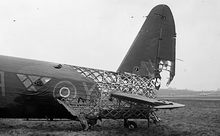
The Old man was with 463 and was called out to attend a Wellington crash. It was an odd one, the bombs had been dropped, most of the skin aft of the fuselage aft wings had been burned off. Eventually a report came through from the Red cross, that the crew were safe in Dulag Luft. The Wimpy on autopilot had flown herself home until he had flown into rising ground. Pic is not of that incident.
 

Attachments

  • Wellingto 220px-Mark_X,_HE239_'NA-Y',_of_No._428_Squadron_RCAF_(April_1943).png
    Wellingto 220px-Mark_X,_HE239_'NA-Y',_of_No._428_Squadron_RCAF_(April_1943).png
    29 KB · Views: 4
The Old man was with 463 and was called out to attend a Wellington crash. It was an odd one, the bombs had been dropped, most of the skin aft of the fuselage aft wings had been burned off. Eventually a report came through from the Red cross, that the crew were safe in Dulag Luft. The Wimpy on autopilot had flown herself home until he had flown into rising ground. Pic is not of that incident.
Yeah, the Wellington has an absurdly strong frame. I'm honestly curious if semi-monocoque had any real advantage (other than simplicity of construction, ability to stretch and adapt the airframe over time, and all that j/k) if metal skin is used instead of doped Irish linen.
 
Last edited:
In theory, using WWII levels of material and design technology, aircraft airframes in the range of the Mosquito to Wellington would have various levels of advantage when constructed using the geodetic methods as developed by Barnes Wallis, vs the contemporary conventional monocoque methods. The areas of advantage would be increased unobstructed volume and/or increased G load limits and/or weight savings.

On significantly larger and/or faster airframes you have a problem where the various bending and twisting forces become too large for the geodetic construction without significant reinforcement in the terms of stringers and formers, with subsequent dynamic twisting of the wings (similar problem to the wing twist on the Spitfire due to the thin wing) and flexing of the fuselage, resulting in various control problems. The dynamic pressures (both in terms of wing loading and in terms of ballooning/loss of lift and destructive pressure differences) on the skinning preclude the use of fabric covering. There is also the problem of how many points of potential failure are allowable and what form they take. Even the Wellington had stringers and ~spars that ran from the nose to the tale, and from fuselage to wing tip.

FWIW, my opinion is that the Windsor was pushing the limit a bit too far for WWII levels of geodetic technology.

If you get too small (using the fighter sized airframes like the Mustang down to Bf109 for example) you could keep the increased unobstructed internal volume at the cost of any practical weight advantage, although you might have a 20 G ultimate load factor at the same weight. If you try to decrease the geodetic structure weight much further you end up with structural elements that become more and more difficult to manufacture and assemble - in effect you end up with an incredibly strong shell that weighs the same or a bit less than a monocoque airframe but costs ~2x as much (maybe significantly more depending on how much you try to decrease the weight). Very high speeds (say 400 mph+) preclude the use of fabric covering on the wings. So basically, you could maybe have made a geodetic structure Hurricane with metal skinned wings, but it would be pointless to attempt the same with the Bf109, Spitfire, Mustang, etc.
 
Last edited:
FWIW, my opinion is that the Windsor was pushing the limit a bit too far for WWII levels of geodetic technology.
Barnes Wallis seems to have thought so as well. From a recent article in Aeroplane on the Windsor.

"....The Wellington and Warwick's geodetic structure had been relatively simple, but the Windsor wing geodetics required heavy back-to--back --channels at the root and lighter single channels outboard, which introduced many new and different joints, so any simplicity was lost.

In addition, the fabric covering that had proved adequate for the earlier type could not provide a surface finish good enough for the Windsor's higher speeds. As a result, Wallis developed a composite fabric covering that eventually - after some problems - introduced fine grade high-tensile steel wires running through the fabric in the spanwise direction. These were clamped to the structure at regular intervals and tensioned tight on the upper surface."

There were only 3 prototype Windsor's produced. - DW506, DW512 & NK136 produced in that order. According to a report signed by Wallis in July 1944 these were some of the changes incorporated into NK136:-

Inner & outer wings had strengthened spars and geodetics
Strengthened aileron, fuselage and tailplanes structures.

Early trials with DW506 revealed problems with the flexing of the fuselage structure. It was lost during testing in March 1944. DW512 first flew in Feb 1944, with NK136 following in July 1944. The last was heavier & 24mph slower at high altitude as a result.
 
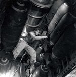
In the picture of the gentleman (armorer?) standing on the bombs, he is either inserting the tail fuze or he is installing the tail fuze's arming wire. Given that there are 4 bombs stacked on the bomb rack, these are 500 pound bombs. Note the bulkhead with the No Smoking decal behind the armorer. That's the front part of the wing as it passes through the fuselage.

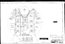
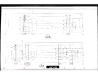
See the attached engineering drawing(15-8810, sheet 7K), which is for the 500 pound bomb hoist installation. You can see the 4 high stack of 500 pound bombs. The drawing is in two images because of its size. Along the bottom are circled numbers representing zones. The tic marks between the zone numbers are 10 inches apart in the full size, single page, drawing. The 15-8810 drawing is 14 separate sheets covering the bomb hoist installation for the following bomb weights (in pounds): 100, 115, 125, 140, 250, 300, 325, 350, 500, 1000, 1600, 2000, 4000.

Another set of drawings (not attached) notes the length of the B-29 bomb bay doors. For the forward bomb bay doors it is 163.85 inches. For the rear bomb bay doors it is 162.46 inches.

Here is a link to a 3D walk through of T Square 54, the B-29 at the Museum of Flight. You can look around 360 degrees, and walk down the fuselage (see the positioning circles on the floor). The forward bomb bay has bomb racks positioned for 500 pound bombs. You can compare to the positioning in 15-8810 above.
 

Attachments

  • Fuzing_the_bombs.jpg
    Fuzing_the_bombs.jpg
    322.9 KB · Views: 8
  • 15_8810_7k_1.jpg
    15_8810_7k_1.jpg
    4.2 MB · Views: 6
  • 15_8810_7k_2.jpg
    15_8810_7k_2.jpg
    540.9 KB · Views: 7

Users who are viewing this thread

Back