DB-601 parts revisited

Ad: This forum contains affiliate links to products on Amazon and eBay. More information in Terms and rules

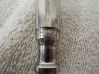
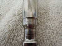
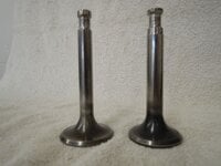
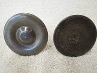
I'm back from the Freeman Army Airfield Museum seeking some additional information. Our president was doing some reorganization in what we call the "dig room", where we have parts that were buried in the late 40s, and dug up in the late 90s, but have not yet been cleaned up or identified. He came upon a whole lot of engine valves, so let's start there. There are 2 different types, with different dimensions, but the stem shape suggests they are related. There are 8 of one type and 11 of the other. Probably intake and exhaust. Since we have one cylinder head for the 601, I'm guessing these valves are from that engine. 24 valves (12 of each) would be a complete set. The most noticeable difference between the 2 valves is the diameter of the stem. One is 14mm; the other is 16mm. The 14mm stem one is about 123mm long, and has a head diameter of 55mm, and has the number 4 stamped into the face of the valve. See pictures. The 16mm stem valve is 121mm long and the head diameter is a little smaller at 51.7mm. There is nothing stamped into the valve face. It didn't clean up as well, leading me to believe it is probably the exhaust valve. At the stem end, in the level just before the stem goes to the full 16mm diameter, it is stamped with the letters CV, then what looks like an inspection stamp, followed by A031. The 14mm stem valve has no markings, other than the 4 in the face. So, Engineman, are these DB-601 valves, or am I barking up the wrong tree?

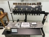
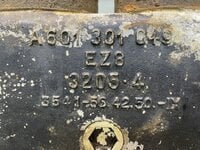
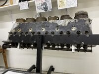
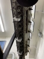
While on the subject of the DB-601, we finally got our one cylinder bank on a stand, and oriented properly (half of an inverted V). A picture of the whole display is included. The cylinder bank has a whole lot of markings cast into the side. I took a closer picture of that portion. Do all those letters and numbers tell us anything more about the engine?

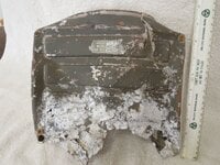
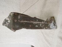
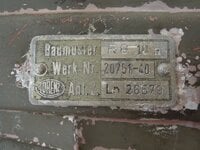
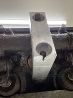
The last item probably has nothing at all to do with the DB-601 engine. It is what appears to be a stamped aluminum cover of some sort. It is about 10-inches by 10 inches by 2.5" deep, and has a very nice data plate attached. I took a picture of the data plate in macro mode. As nearly as I can tell, the first line says Balmuster RG. 10 a, the 2nd line Werk Nr 20751-40, and the third is is an oval logo that says LORENZ, followed by Anf. Z. Ln 26579. I'm not sure if the last character in the first line is a lower case "a" or not, but that's the best I can do, even with a magnifying glass. What does the cover go on?

That's it for this evening. Thank you for your help. ----- Larry DB-601 valves.JPGValve faces.JPGStem markings 1.JPGStem markings 2.JPGAluminum cover.JPGEdge of cover.JPGCover dataplate.JPGCylinder bank on stand.JPEGCylinder bank markings.JPEG
 
Hi Larry,

The valves you show are from a DB 605 (various, includes DB 610) type engine. The 14mm stem ones are inlet valves, the 16mm stem ones are exhaust valves. The identification includes all the sizes you give, and that proves they are DB 605.

The cylinder block is a right hand item, from a DB 601, probably a 601A.
The A 601 301 049 is the part number.
EZ8 is possibly the production location/plant.
3205.4 is the material code for the alloy casting.
the 3541, etc bottom row of numbers will refer to details of production of some sort. This block will have the engine serial number stamped at the rear, by the cam drive, and the cam drive housings will also have the engine serial number stamped on their flanges. The piston sticking out will also have many details stamped on the underside, if it is not too corroded?

Cheers

Eng
 
Thank you, Engineman. Now I can make new signs, with correct information, about the cylinder bank. There is a piston in each cylinder, but they are corroded in place. I will have to make a fixture to hold the valves for display, after I get the rest of the valves cleaned up. We have a cam to go with the cylinder bank, but we need to fabricate the retainers to hold it in place. ----- Larry
 
RG 10A, Röhren-Gerät RG 10a Military Militär verschiedene Hersteller gleicher |Radiomuseum.org

Thank you mjfur. I went to that website, but it is all in German. How can I get it translated into English so I can tell what the item really does? I understand that it is a piece of radio equipment. ----- Larry
 
Hi Larry,

Yes, the cam-carriers were magnesium. Restorations often have replacements made in aluminium.
You may be aware that exhaust valves were a big problem for the Germans, they couldn't get enough Nickel for the steel-making requirements.

Eng
 
Thank you mjfur. I went to that website, but it is all in German. How can I get it translated into English so I can tell what the item really does? I understand that it is a piece of radio equipment. ----- Larry


FuG 10 / radio system

Development for the FuG10 began in 1936. Series production began in 1938. The FuG10 system had a transmitter for longwave (300 – 600 kHz) and one for shortwave (3.0 – 6.0 MHz). From 1939 onwards, larger aircraft with several crew members were preferably equipped with it (e.g. Ju 88, He 111, Do 217, Me 110).
The FuG 10 device set was declared the standard type. Lorenz and numerous licensed companies built almost 100,000 systems by the end of the war.
The test panel shown in the pictures below was used to test the individual devices on the ground, but could also be used as a ground radio station at field airports.

FuG10 test set ...
FuG10-1024x808.jpg


FuG10-2-1024x795.jpg

the pic source: Ln.XXX Prüftafel PT10, FuG X (FuG 10) | Deutscheluftwaffe

The RG 10a included an amplifier for the flight crew's self-communication (EiV - the on-board intercom), a listening device (tone generator and amplifier) for A1 transmission operations and a pulse generator and amplifier for pulse transmission operations. The "impulse sending" operating mode was banned from 1940 and existing systems were converted. The EiV amplifier was used in the "Telephony transmission on shortwave" operating mode as a modulation amplifier for the HF transmitter of the FUG 10 system.
The RG 10a was equipped with 5 tubes (devices without impulse), with 7 tubes (devices without impulse, amplified output stage of the EiV system) or with 9 tubes (with impulse).

 
As an eBay Associate we earn from qualifying purchases.
Hi Larry,
I do not know for sure who has reproduced the cam-carriers, or who has a CAD design or 3D Print program. The cam-carriers are all similar in the DB600 series V-12 but are specifically different on different versions of the engines.
If I was looking at making repro carriers for a static exhibit like yours, I would consider scratch-building some alloy repro's for the middle 5 carriers, which are all similar, leaving out the front and rear ones which are both different, the rears being quite complicated.
The basic carrier is an oval section tower, with two through stud holes, and split at the camshaft c/l with a cap. Of course, the real item is quite complicated but, to just hold the camshaft in place for display, simple solid alloy bar stock of suitable size could be turned-oval, bored and cut to make suitable simple carriers and caps.
You do have the issue of the valves, which will be solid and all at fully seated, I guess? This means that the camshaft cannot sit fully in place because in whatever position you put it, some of the valves will need to be open. So, even genuine parts or copies would not suit, unless valves can be moved, and the original studs will be too short.
Being pragmatic, I suggest that you could simply make some wooden cam-carriers to suit. As you know, done well, wood is a good display material and can be painted to blend-in.
I hope my thoughts are useful?

You might be interested in the video's on youtube of a static DB 605. Search on youtube for "TEAM DB 605", there are good pictures of the valvegear on the "it's alive" vid.

Cheers

Eng
 

Users who are viewing this thread

Back