Engineman's WW2 Aircraft Parts Quiz!

Ad: This forum contains affiliate links to products on Amazon and eBay. More information in Terms and rules

I often have wondered why there are so few vdm documents.
Hi Snautzer,
Yes, I agree. There are enough documents to understand, if you research, but it is not easy as they are scattered and bloody difficult to find. In actual fact, there is possibly enough of a void for me to compile a book about the tech details of the VDM props and the Tech to go with it but, I doubt that any publisher would make it worthwhile. Tech does not sell well, even if you try to make it interesting. Take a look at Callum Douglas' fantastic co-authored book "Turbo/Supercharger Compressors and Turbines for Aircraft Propulsion in WWII" (TSCT). That is a Masterclass in the subject, but no publisher would take it as a print-run and it is on-demand expensive. I agree, it is technical but, it can be read by anyone and it is Superb to me.
So, unless I win the lottery, I won't be self-publishing anything!
Cheers

Eng
 
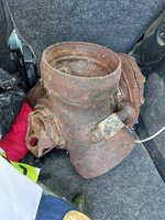
Excellent explanation and images. I thought they were bigger. This one came from a Battle of Britain Bf110 casualty in Dorset, UK.
 

Attachments

  • 20230830_105105.jpg
    20230830_105105.jpg
    3.6 MB · Views: 19
Excellent explanation and images. I thought they were bigger. This one came from a Battle of Britain Bf110 casualty in Dorset, UK.
Hi ian,
Yes, that looks correct. Looks like the propeller shaft is snapped just behind the hub? The dark-green paint of the hub is usual at this time. You can see that the hub nut is the early type that has large holes for a long bar to tighten or loosen, instead of the eight dogs that came later with blast-tubes. Certainly some BMW 801 engines with no blast tube also had the hole-type nut. This prop hub is quite different in detail to the DB 601 E / DB 605 etc. However, the operation is the same.
Your hub will have the type and serial numbers stamped into the metal at the front outer edge, just before the step at the front. You should have a good look. There should also be a soft alloy id plate rivetted-on, but that might be gone. I would be interested in your numbers, I might have some similar to compare!
The mangled prop nut could be difficult to remove. You can see the two lock-screws that are wirelocked, they engage into the holes in the propshaft to lock the nut. Also, the impact has broken the nut and the snap-ring has partly broken the bronze split cones. This is one item that you have to consider either leaving in one-piece, or doing a certain amount of mechanical work on to dismantle it. The steel is very high quality, you cannot easily cut or drill it, it takes high grade drills and cutting discs. What are your plans for it?
Cheers

Eng
 
"
Hi ian,
Yes, that looks correct. Looks like the propeller shaft is snapped just behind the hub? The dark-green paint of the hub is usual at this time. You can see that the hub nut is the early type that has large holes for a long bar to tighten or loosen, instead of the eight dogs that came later with blast-tubes. Certainly some BMW 801 engines with no blast tube also had the hole-type nut. This prop hub is quite different in detail to the DB 601 E / DB 605 etc. However, the operation is the same.
Your hub will have the type and serial numbers stamped into the metal at the front outer edge, just before the step at the front. You should have a good look. There should also be a soft alloy id plate rivetted-on, but that might be gone. I would be interested in your numbers, I might have some similar to compare!
The mangled prop nut could be difficult to remove. You can see the two lock-screws that are wirelocked, they engage into the holes in the propshaft to lock the nut. Also, the impact has broken the nut and the snap-ring has partly broken the bronze split cones. This is one item that you have to consider either leaving in one-piece, or doing a certain amount of mechanical work on to dismantle it. The steel is very high quality, you cannot easily cut or drill it, it takes high grade drills and cutting discs. What are your plans for it?
Cheers

Eng
Prop_Retaining Nut DB603
 

Attachments

  • DB603_Prop_Lock_Nut.jpg
    DB603_Prop_Lock_Nut.jpg
    627.7 KB · Views: 17
"

Prop_Retaining Nut DB603
Very nice Tony, The big brother of the DB 601 E / DB 605. You can see inside the nut, the threads at the rear for the propshaft, with the holes for the vernier effect locking stopscrew that engages with the tangs on the front of the propshaft.
Then at the forward end of the inside, you see the threads that engage the blast-tube extension, when fitted.

Eng
 
Here is the Bf 109 F3/4 to K blast tube extension. This stops the muzzle blast destroying the spinner. The tube snugs-up to the front edge of the propshaft and the large dia ringnut screws into the front thread in the propnut, securing the extension in place. The locking screw fits between the propnut dogs in a vernier fit to the threaded holes in the ringnut.
The DB 603 version would be similar where a blast tube was required.

Cheers

Eng

120_3116.jpg
 
Hi ian,
Yes, that looks correct. Looks like the propeller shaft is snapped just behind the hub? The dark-green paint of the hub is usual at this time. You can see that the hub nut is the early type that has large holes for a long bar to tighten or loosen, instead of the eight dogs that came later with blast-tubes. Certainly some BMW 801 engines with no blast tube also had the hole-type nut. This prop hub is quite different in detail to the DB 601 E / DB 605 etc. However, the operation is the same.
Your hub will have the type and serial numbers stamped into the metal at the front outer edge, just before the step at the front. You should have a good look. There should also be a soft alloy id plate rivetted-on, but that might be gone. I would be interested in your numbers, I might have some similar to compare!
The mangled prop nut could be difficult to remove. You can see the two lock-screws that are wirelocked, they engage into the holes in the propshaft to lock the nut. Also, the impact has broken the nut and the snap-ring has partly broken the bronze split cones. This is one item that you have to consider either leaving in one-piece, or doing a certain amount of mechanical work on to dismantle it. The steel is very high quality, you cannot easily cut or drill it, it takes high grade drills and cutting discs. What are your plans for it?
Cheers

Eng
I was collecting this hub for a friend, back in the summer, but I do have the other hub, so will look for the part numbers. The labels were indeed missing, usually rubbed off in a high speed crash, and this one had buried itself 25 feet down. It was Bf110 C-7, recovered in 1985. It will be part of an online museum, at wingleader.co.uk, but not in there yet. Lots to do!
6./ZG 26 Luftwaffe
Registration:3418
MSN:3U+JP, gelbe J
Fatalities:Fatalities: 2 / Occupants: 2
Aircraft damage:Destroyed
Location:Kingston Russell Dairy Farm, Long Bredy, Dorchester, Dorset, England
John Vasco John Vasco perhaps of intrest.
 
Lastly for here on the VDM propellers, there is the thorny subject of how the clock style pitch indicator should function. This "clock" shows blade pitch in a normal analogue clock display, where "10 minutes" equals 1 degree of blade pitch change. The "12.00" (twelve O'clock) position is the Take-off setting and the "clock" moves anti-clockwise as pitch is increased with greater airspeed. So, "10.30" would indicate that the blade pitch had changed "90 mins" earlier than "12.00", so the blade pitch would now be 90 divided by 10, equals 9 degrees coarser than the "12.00" setting. This indication is simple, Faster airspeed equals anti-clockwise movement, Slower airspeed equals clockwise movement. This is stated in VDM documentation.
Unfortunately, mistakes in translation or examination have caused misunderstanding of this system. One of the worst mistakes is in an American Intelligence T-2 Air Material Command, Wright Field document, Project No DP-154. This document states the opposite sense of function on page 12, in the VDM section, part 4 a (4) "The Electrical Pitch Indicator". The example given is a pitch indication of "03.30" and says this is 3x6 plus 3x1 equals 21 Degrees high pitch above Take off position, which is incorrect for the proper operation of the VDM system. This mistake is probably because the indicator they examined was set to the wrong direction of operation in the reversing A/B switch. The correct indication for "03.30" would be read the other way! 8 x 6 plus 3 x 1 equals 51 degrees coarser than the "12.00" take-off setting, which would be effectively fully-feathered. This is an unfortunate mistake on an otherwise excellent tech document. But the importance should not be underestimated because I know of aircraft with this system that have been operated with incorrectly set pitch indicators. Fortunately, most vintage VDM prop operators are now aware of this. Also, BTW, the furthest fine pitch that can be set is about "12.30" on the indicator, which is just 3 x 1 equals 3 degrees Finer (Lower pitch) than the Take-off setting.
Sorry if that is a bit teccie, but it is helpful to know that anti-clockwise is coarser pitch on your Bf 109 flight-sim! (and all other VDM propeller installations that are correctly set-up!)

Cheers

Eng
 
Last edited:
So now for something completely different!
These are a pair, aircraft parts, they are fitted on the outside of the aircraft. Any offers?

Eng

114_3071.jpg
 
Last edited:
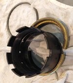
And now, to the use of the spanner. There are not many specifics but, the VDM manual is probably best. It shows the spanner being used to loosen or tighten the prop nut with a blade held on a rigid stand with fabric packing to protect it. The illustration below is from the Bf 109 G maintenance manual. You can see that the spanner has a simple tube extension that is about a metre long. To tighten the nut, the same proceedure is used, but torque loadings are not given! However, there are illustrations in the VDM manuals that show a man hanging on the extension bar, so that is about 150lb x 4ft = 600lb/ft.
BTW, the VDM prop is seated on Bronze 45degree cones and there is a large snap ring that engages a groove in the front hub aperture to give self-extraction off the cones.
Hope this is interesting!

Eng

View attachment 760051
That seems like a small nut to hold/clamp the prop to the engine. However, my only first hand prop experience was the props on the C-119. And, after all, I was only an apprentice assistant propeller repairman.
 
That seems like a small nut to hold/clamp the prop to the engine. However, my only first hand prop experience was the props on the C-119. And, after all, I was only an apprentice assistant propeller repairman.
Hi special ed! Well, I agree it is smaller than many. However, it is maybe bigger thread-wise than Merlin. Certainly the Torque is not that high, I have done Dart turbo-props with something like 1100ft/lb as I recall? I think the power and prop size is not huge, prop is only 3.0m dia, some transport props are pretty huge.
The illustration shows just the one guy doing the job, mind you he is not going to lift the prop off himself, the alloy bladed ones are fairly heavy. Another thing the VDM props have but the books don't say much about, is that they have a master half-depth spline! That can be fun if you don't know! I am still not certain why they did that, the whole assembly is equally balanced, I think they just got anal about having everything related to datum, all the components of the hub are position numbered.

Cheers

Eng
 

Users who are viewing this thread

Back