Basically, I was kind of referring to the modification of the rear that sort of blended the taller tailwheel into a tear-drop when retracted.
This image you posted earlier, but I'll use it for an example...
View attachment 576522
Good point.
In fact, I also considered that possibility, but the It should be visible at the ground, was not found in the included photo for F4U-1 BuNo.17930 report and others.
And I actually found a 'block' in the attached F4U-1 BuNo.17930's photo. I guessed with it the block mentioned in the report because the block was not found on the high tail wheel of the F4U-1s in service.
But it is possible that you are correct, as I wrote above, I also have made the same guess as you.
Because I have a photograph of it installed on F4U-1 BuNo.17930
In this case, I miscalculated what was called 'block' and the specificity of F4U-1 BuNo.17930 is further reduced.
When I saw the old guess again from you, I began to get confused again and began to feel as if my old guess was right. I mean, I think your guess is right.
I realized again that I knew too little about this beautiful aircraft.

While this may/may not sound ignorant: I'm curious why they went to the whole trouble of redesigning the whole tailwheel? Was this related to visibility?
If the performance was most considered, the smooth surface of the first batch F4U-1's tiny tailwheel unit and the slotless tailwheel door, would have been the best. It seems to me that continued improvements to the tailwheel section are related to improved landing capabilities. As noted in the old post, it affected performance but was slight, on the other hand, landing capabilities would have come as a greater issue for the F4U-1, which targets carrier operations.
What caused there to be such discrepancies between the drag-coefficient chart and the itemized chart that displayed methods to increase speed?
Charts from the Navy and NACA reports appear to be based on lift cofficient for level flight(about 0.2). But the other appears to have been zero lift drag coefficient chart. so instead of applying it as it is when I use it, I only made a relative comparison based on the data actually obtained from flight and calculation. In addition, NACA's drag coefficients were averaged figures, and even with similar commented drag reduction, there may be slight differences in actual work for drag reduction to F4U-1.
Looking at this image...
Was it possible to fair over any of these plates for an operational aircraft? As for the fairing over the wing-fold line, was this done on land-based aircraft?
According to Dana Bell, the wing fold seams were taped, puttied, and smoothed. As the attached photo shows, Some Corsairs even carried a "Wings Won't Fold" warning.
Wait, they could have made improvements to the engine cowling?
They did, with F4U-4 and other post war variants. but that's not what you're trying to say.
Air leakage creates drag, so if faired it and make smooth surface, the drag coefficient will decrease.
The above picture is F6F-3's cowling with a total of 6 cowling flaps, 3 on each side. for drag reduction, faired cowling-flaps and hinge line-gap-leakage gives 3 mph.
Assuming that the F4U-1 BuNo.02390 had 18 cowl flaps because there was no mention in the report that the fixed upper plate was installed, because there was more air leakage, it can be expected that making a smooth surface by fairing it is more likely to achieve more performance.
Actually, even with the 13'1" blade -- it's still supersonic at the tips. It's just not quite as extreme 1.0699 vs 1.0791 within 200 feet of each other in altitude. That said, with the F6F's propeller you're going 6 miles an hour faster at the same altitude.
View attachment 576539
View attachment 576540
Then perhaps a major change in design has affected it than tip speed. The old 13"4' propeller was called the narrow chord prop and the new 13"1' was called the paddle blade prop.
And I have a few points to make. The performance of the first batch birdcage F4U-1 with 395 mph Vmax and 348 mph at S.L, which you labeled 1944/7/28, was actually measured in 1943/1/28 and F4U-1D's detail specification was company estimated figures. too many differences and variables exist between the two samples - between actual first batch birdcage F4U-1 and company estimated F4U-1D. In order to know the performance achieved by the new propeller, except for the propeller, the same power, same airframe and same drag condition will be required.
I think I've already introduced samples that are 'standard' to compare the 13'4" propeller with the 13'1" propeller. F4U-1 ACP and F4U-1 BuNo.17930 with 'standard' drag conditions by the Navy and measured performance in similar period(1944/3/1 for ACP and 1944/3/4~1944/3/8 for F4U-1 BuNo.17930).
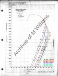
Cross-validation with ACP and F4U-1 BuNo.17930 well shows both the matching and difference of performance that should be between the 13'1" propeller and the 13'4" propeller under the same drag condition. It showed the characteristic of a 13'4" propeller losing efficiency in a high-altitude high-speed range above 16.5k ft, while at the same time the two F4U-1s show well matching performance(or showed a convincing similarity) at same drag conditions below 16.5k ft. according to this, If make a comparison at same altitude for military power as you did, the 13'1" propeller was abuot 8 mph faster at 25,000 feet.
In conclusion, the Navy succeeded in correct the F4U-1 BuNo.17930 to 'standard' drag condition for production F4U-1(F4U-1 ACP), and as a result of installing a new propeller, it seemed able to clearly identify the performance that could be achieved compared to the old propeller. I recommend using these for calculation because it's Navy corrected samples to military standard that well showed the performance difference caused by the replacement of the propeller for F4U-1 at same and standard condition.
If I read this right, the test involved a 13'0" propeller instead of the F4U-1's 13'4", or the F6F-3's 13'1" design. The gear ratio was also 0.4 instead of 0.5. So the ability to estimate performance to within 500 feet was pretty decent at the time?
F4U-1 BuNo.02334's four-bladed propeller would be closer to F4U-4's because it was also four-bladed propeller with 0.45 gear ratio. and the propeller's diameter seems affected not only by the propeller blade design, but also by other units. for example F4U-4's propeller diameter was 13'2" with 6501A-0 blades but F4U-1's propeller diameter was 13'1" with same 6501A-0 blades. And the report described F4U-1 BuNo.02334 that the new propeller(6501A-0) was installed 'instead' of the old propeller(6443A-21), the 'standard' F4U-1 mentioned in the report would have had an old propeller(6443A-21).



