Flared and Flareless compression tube fittings in hydraulic and fuel lines (1 Viewer)

Ad: This forum contains affiliate links to products on Amazon and eBay. More information in Terms and rules

Nice link Denys so it saves me trying to demonstrate with photos the differences in AN and AC fittings.

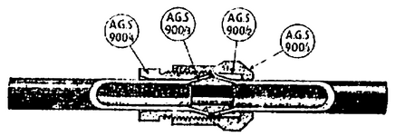
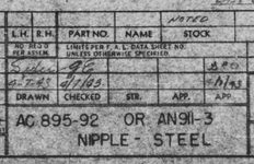
Attached are couple of references to US prewar civil and military aircraft fittings that may be of interest to some. Note the Fletcher handbook is using the Parker part numbers like used on the DC-2 but the DC-2 used the "triple tube coupling" system as does the AN system. The AC may have used the "standard" coupling for some installations but I have never seen it used on aircraft.

1658901123177.jpeg


1658901260981.png
 
This should clarify things


You also need to note that the British used their own system which is generally similar in concept but differs in the threads, angle of the cone etc. It's reference is part of their AGS syste of aircraft hardware.

cheers
Thank you, the link did help.

So this is what I have up to now on prewar and WW2 aviation tube fittings for fuel, oil, and hydraulic lines.

AC (Air Corps) standard - flared 35 & 45 deg. (US) - with 45 deg. flared fittings also being a standard in the automotive industry
AN (Army/Navy) standard - flared 37 deg. (US and foreign metric equivalents)
AGS (Aircraft General Stores) standard, assuming flared 37 deg? Some type of DEF-STAN postwar?

Ermeto EO flareless progressive ring (single ferrule) tube fittings in Germany and maybe elsewhere (unclear when Parker purchased)

Other flareless single ferrule compression type tube connections for things like lower pressure brake lines.

Germany - metric 37 deg flared and Ermeto EO flareless fittings?

Assuming the French had their own fittings because of the their mature aircraft and auto industries, but no idea what the Soviets and Japanese adopted. Can only imagine what it would have been like to be a aircraft mechanic in Finland or China.
 
The Brits used several different fitting combinations in fluid (hydraulic/fuel/air pressure/vacuum/etc) systems. As I was told at the beginning of my training - there are three ways to build an aircraft - the right way, the wrong way, and the British way.

Starting with flared systems - they only had one flare angle - I don't know what the angle is because you only need the one tool kit for British flares instead of two for US aircraft - or one after about 1940. That said the Brits make up for it in multiple ways of using the flare and creating assemblies that make you hate working on British aircraft.

This is a typical flare fitting and a cutaway diagram of how it assembles. My apologies for the sh*t photos that follow.
1659149130162.png
1659147637006.png


This is a different way to use parts 1 & 2 above (now ID'd as 3 & 4) with some other parts to produce a similar joint
1659149514211.png
1659152106147.png


Now parts 1 & 2 become 2 & 3 and there is an adaptor so that the flared tube can connect to a fitting which requires a spherical end.
1659149742883.png


Confused yet - well lets throw in a different version of item 4 above - which conveniently shows the spherical fitting diameter as S
1659150119720.png


Well now - from that the Brit angle is 32 + 1/2 degrees - that's good I learned something today.

That spherical end is not to be confused with the 60 degree cone used on some other fittings
1659150850899.png


Which are used with silver soldered end fittings like this - again **** photo
1659151278621.png

1659150600610.png


And naturally there are fittings and combinations that have a foot in each camp like these - note that the olive in this one is a different shape and part number to the similar one above.

Did I mention the right way, the wrong way, and the British way? Or that I hate working on British aircraft? Or that on top of AGS specs there are BS specs from Bristol and that other companies had their own specs? The latter is not only a British trait though - Curtiss and Lockheed had a bad case of that mental illness as well.
1659152222932.png


1659151487692.png

1659151015559.png


And then there are the flareless fittings like these used in low pressure systems - the black ring is made of a rubber compound

1659151131602.png


Among other connections the Brits used this is one from the Anson brake system.
1659148645136.png


Did I mention the right way, the wrong way, and the British way? Or that I really hate working on British aircraft?
 

Attachments

  • 1659150521735.png
    1659150521735.png
    84 bytes · Views: 25
  • 1659152163225.png
    1659152163225.png
    8.4 KB · Views: 23
As I was told at the beginning of my training - there are three ways to build an aircraft - the right way, the wrong way, and the British way.

Starting with flared systems - they only had one flare angle - I don't know what the angle is because you only need the one tool kit for British flares instead of two for US aircraft - or one after about 1940. That said the Brits make up for it in multiple ways of using the flare and creating assemblies that make you hate working on British aircraft.
Many years ago got to work on a Hunter and later a Jet Provost, yep!!!!
 
This is a page from a 10 page Boeing Standard on Tubing and Fittings. It calls out the flare angles for various tubing diameters, while the rest of the document covers preparation, cleaning, tubing color coding, pressure testing (for hydraulic, pneumatic, fuel, de-icer, etc.) and so on. The AC flarings are spelled out, while the AN flarings are in another non-Boeing document (AND10061). This is more for historical reference since AN fittings seem to be the preferred fittings starting in the mid-1930's.
 

Attachments

  • BAC 5001 p 2.pdf
    805.7 KB · Views: 49
All the established US aircraft manufacturers were still using a lot of AC hydraulic fittings throughout WW2 and in the 1940/42 new design aircraft there was a very high percentage of AC parts so I think your time line is a little optimistic. I would have put the start of AN fittings as very late thirties at the earliest.
It may well be, however, that AN started mid 30s in bolts and other fasteners and that fluid couplings - being in the 8nn and 9nn range did not transition to AN until much later in the process.
This spec drawing shows that the AN 911 nipple was first approved on 6 Jan 1941. I cannot find a similar spec sheet for the first edition of the AN3 series bolts but the oldest version of that sheet I have is dated 10 May 43 and I am sure that the AN3 spec predated that.
1659504940897.png
 

Attachments

  • 1659504838712.png
    1659504838712.png
    132.2 KB · Views: 22
Just picked up a copy of this book dated 1943 and the author is obviously way behind times as AN was well and truly the main hardware on new designs by then. It does show most of the Parker hardware used on the DC-2 though and so I have posted it for the benefit of anyone else working on aircraft of that vintage. It clearly shows why the far simpler AC and AN part numbering system was necessary.

1660418332318.png


The section on hydraulics is all AC and Parker fittings.

1660418044005.png

1660418116696.png
 
MiTasol MiTasol Thank you for the manual scans. I came across this photo of a oxygen valve on Twitter yesterday posted by the group rebuilding the PR Spitfire AA810. I'm never going have the chance to be part of WW2 restoration, but these details details are cool.

original tweet: "Recently the project acquired this crash recovered oxygen tap which combined with our oxygen bottles and fittings nearly completes all the items we need for the oxygen system. In the Spitfire it fits on the starboard cockpit wall. #aa810 #Spitfire"
D230B3A1-0E29-418A-8AB9-EC0999E85699.jpeg
 
Last edited:

Users who are viewing this thread

Back