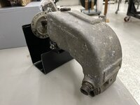
Fuel Evaporator

Ad: This forum contains affiliate links to products on Amazon and eBay. More information in Terms and rules

I think I'm asking for some help from Engineman on this one.

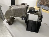
We (at our museum) have identified a part we believe is a fuel evaporator for a Jumo 211 engine. The 211 was used on the Ju-88 aircraft. We have several other parts for the Ju-88. My questions are: a) What function does a fuel evaporator perform, and b) where on the engine was it located? A picture of a Jumo 211 engine, with the fuel evaporator pointed out, would be very helpful. I'm asking these things because I need to make an exhibit sign, explaining it to museum visitors.

Thank you for your help.

Larry
 

Attachments

  • Fuel evaporator for Jumo 211 engine.JPEG
    Fuel evaporator for Jumo 211 engine.JPEG
    635 KB · Views: 43
  • Jumo 211_fuel evap1.JPEG
    Jumo 211_fuel evap1.JPEG
    413.2 KB · Views: 41
  • Jumo 211_fuel evap2.JPEG
    Jumo 211_fuel evap2.JPEG
    374.5 KB · Views: 47
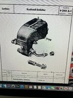
Yep ... in other words ... the Kraftstoff-Entlüfter means a fuel breather and an air separator in the fuel system. This device played a key role in ensuring stable operation of the injection pump by removing air bubbles and gases from the fuel before it was fed to the pumping sections. According to Junkers technical documentation, the Kraftstoff-Entlüfter was located in the supply circuit between the fuel filter and the injection pump.It was responosible for preventing air from entering the injection pump, which could lead to engine stoppages or stalling, maintaining a continuous stream of fuel flowing to the injectors and removing fuel vapors that could be generated as a result of the installation heating up near a hot engine block.

It looks like the Kraftstoff-Entlüfter 9-2105 A-1 worked with the Junkers Einspritzpumpe 9-2009 D-1. It is quite to difficult to notice where the devices were mounted because these were fixed at the bottom of the engine between the cilinders. I hope the bottom diagram may be useful.

jumo_211_b-d_und_g-h_einspritzanlage_seite_04_k1.jpg

jumo_211_b-d_und_g-h_einspritzanlage_seite_04_k2.jpg

9-2009_d-1_einspritzpumpenaufhaengung.jpg

jumo211a-1_kraftstoffsystem2.jpg

the pic source:
Junkers Einspritzpumpe 9-2009 D-1
 
I think I'm asking for some help from Engineman on this one.

We (at our museum) have identified a part we believe is a fuel evaporator for a Jumo 211 engine. The 211 was used on the Ju-88 aircraft. We have several other parts for the Ju-88. My questions are: a) What function does a fuel evaporator perform, and b) where on the engine was it located? A picture of a Jumo 211 engine, with the fuel evaporator pointed out, would be very helpful. I'm asking these things because I need to make an exhibit sign, explaining it to museum visitors.

Thank you for your help.

Larry
Hi Larry,

The info given by Wurger is correct and his link to the website Junkers Einspritzpumpe 9-2009 D-1 at Junkers-EP.de is the best there is, easy translated as well.
Overall, the development of the Junkers fuel injection pumps was quite complicated, with many revisions and updates that included the factory rebuilding to update earlier versions. Thus, early versions of aircraft and their JUMO 211 engines could have had several different versions of the injection pump, if they survived very long.
The large Entlufter 9-2105 A-1 that you have could have been on the early war versions of the JUMO 211 engine, and was fitted to the Injection pump 9-2009 B-2, B-1 (yes, the B-2 was in service before the B-1), C-1 and D-1 that were developed and updated in that order.
As described, the large Entlufter 9-2105 A-1 you have was designed to catch and remove air bubbles from the fuel flowing into the Injection pump.
The later versions of the Jumo 211 had a different series of injection pumps numbered in the 9-2021 series, and those had a different, smaller, integral Entlufter, that had a spiral flowpath for the fuel that separated the bubbles by centripetal action.

Cheers

Eng
 
Thanks, Tony & Engineman, for the additional information. Now I'm on to an exhibit sign for a magneto for the Jumo 211.

I'm also building a chassis for a flight simulator that replicates a WWII Waco CG-4A glider. (No engines for this one! Sorry. :)) We have all the electronic and control components, and the appropriate software. Right now, it sits on a folding table, and it "flies" just fine. I need to get in into a more appropriate setting. BTW, with a glide ratio of only 12:1, it doesn't actually glide very well either.
Larry
 
Thanks, Tony & Engineman, for the additional information. Now I'm on to an exhibit sign for a magneto for the Jumo 211.

I'm also building a chassis for a flight simulator that replicates a WWII Waco CG-4A glider. (No engines for this one! Sorry. :)) We have all the electronic and control components, and the appropriate software. Right now, it sits on a folding table, and it "flies" just fine. I need to get in into a more appropriate setting. BTW, with a glide ratio of only 12:1, it doesn't actually glide very well either.
Larry

Hi Larry,
Do you want info about Jumo 211 Magneto's? If you put up some pics I should be able to give you detailed info.

Cheers

Eng
 
Thanks, Tony & Engineman, for the additional information. Now I'm on to an exhibit sign for a magneto for the Jumo 211.

I'm also building a chassis for a flight simulator that replicates a WWII Waco CG-4A glider. (No engines for this one! Sorry. :)) We have all the electronic and control components, and the appropriate software. Right now, it sits on a folding table, and it "flies" just fine. I need to get in into a more appropriate setting. BTW, with a glide ratio of only 12:1, it doesn't actually glide very well either.

Larry


If my memory is correct the USAAF cargo glider with the best glide ratio was the glider version of the C-47 but I never went past prototype as they were too valuable as powered aircraft.
 
Last edited:
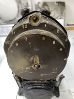
Thanks for the offer of more info. I think the magneto is a Bosch GE12. I'll take some pictures. I would like to know where on the engine the mags were mounted.

Larry

Hi Larry,

Great, looking forward to the pics and then I will tailor my reply. Please include as much detail and data plates as possible.
Regarding the mounting of the Magneto's on the 211, they were positioned very similar to a Merlin, a V-1710 or most other V12 of that time, at the rear, on each side, on the rear gearcase. I will include illustrations.

Cheers

Eng
 
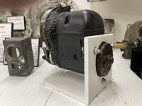
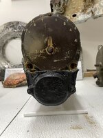
OK Engineman, here are 3 pictures of the magneto I believe is a Bosch GE12, and used on the Jumo 211 engine, among others.

I'm going to start a new thread about a large prop hub. We already have too many subjects in this thread.

Larry
 

Attachments

  • IMG_1594.JPEG
    IMG_1594.JPEG
    358.3 KB · Views: 25
  • IMG_1593.JPEG
    IMG_1593.JPEG
    421.9 KB · Views: 29
  • IMG_1592.JPEG
    IMG_1592.JPEG
    426.9 KB · Views: 25
This post has nothing to do with the Fuel Evaporator or the Magneto discussed in this thread. However, since I mentioned being delayed in providing additional information because I was designing and building a chassis for a flight simulator (Waco CG-4A glider), I thought I would send along a picture of the finished chassis with the computer, monitor, and controls installed. Please see the attached.

Larry
 

Attachments

  • Glider sim_Waco CG-4A.JPEG
    Glider sim_Waco CG-4A.JPEG
    426 KB · Views: 31
OK Engineman, here are 3 pictures of the magneto I believe is a Bosch GE12, and used on the Jumo 211 engine, among others.

I'm going to start a new thread about a large prop hub. We already have too many subjects in this thread.

Larry
Hi Larry,

Thank you for posting these pics of your Bosch GE12 magneto. I enclose a photo of a page from the 1942 Bosch Handbuch for the GE12 Magneto. I think you will see that it covers these items. These wartime magneto versions progressed through development of the B, C and D SERIES, and came in quite a few minor versions for different engines, with versions for Left or Right fitment and, with variations for the HT wiring fitment. Unfortunately, I do not see an exact detail for your particular part, but I think that it is one of the GE12 CRS versions, which were mid-WW2 JUMO 211 fitment. As I mentioned before, the JUMO 211 had two of these magneto's, fitted at the side/rear, similar to a V-1710 or a Merlin engine.
I also enclose a photo of my own GE 12 DRS 195, which was a late War built version for late JUMO 211.

Best Wishes,

Eng

211ge121.jpg
211ge122.jpg
 
Eng, do you have a picture of a Jumo 211 engine with the Bosch GE12 magneto attached, in a way that is readily visible? I searched on the internet, but I couldn't find a picture I really liked. I need a picture to put on the exhibit sign I will create to go with the magneto. ..... Thank you, Larry
 
Eng, do you have a picture of a Jumo 211 engine with the Bosch GE12 magneto attached, in a way that is readily visible? I searched on the internet, but I couldn't find a picture I really liked. I need a picture to put on the exhibit sign I will create to go with the magneto. ..... Thank you, Larry

The magneto was installed at the bottom back of the engine and was attached to the both sides of it. Here diagrams and pictures showing where ...

jumo211a-1_magneto_a1.jpg

jumo211a-1_magneto_b.jpg


the Jumo 211A-1 in the IWM Duxford
jumo.jpg

Jumo211A.jpg

the pic source: Junkers Jumo 211 Survivors
 
Eng, do you have a picture of a Jumo 211 engine with the Bosch GE12 magneto attached, in a way that is readily visible? I searched on the internet, but I couldn't find a picture I really liked. I need a picture to put on the exhibit sign I will create to go with the magneto. ..... Thank you, Larry

Hi Larry,
Here is an image of a JUMO 211 J engine from an Italian Museum. You can see the Magneto.

Eng

211j.jpg
 

Users who are viewing this thread

Back