- Thread starter
- #21
Navigation
Install the app
How to install the app on iOS
Follow along with the video below to see how to install our site as a web app on your home screen.
Note: This feature may not be available in some browsers.
More options
You are using an out of date browser. It may not display this or other websites correctly.
You should upgrade or use an alternative browser.
You should upgrade or use an alternative browser.
Fw 190 parts?
- Thread starter Alfredo
- Start date
Ad: This forum contains affiliate links to products on Amazon and eBay. More information in Terms and rules
More options
Who Replied?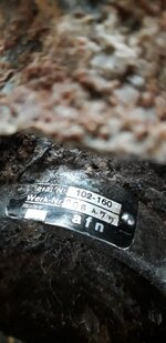
A common part i think and for internal power system
View attachment 780472
View attachment 780473

Fl.32113-12 Steckereinsatz | Deutscheluftwaffe
www.deutscheluftwaffe.de
Having owned and maintained several BMW cars, I am quite sure that this item is a fuse holder - possibly for the instrument panel etc.
I'm aftraid, that's not the fuse holder but a 20-pin plug connection for on-board electrical system. Actually it consists of two parts ( male and female part type ). In the quoted pics just it is seen the Fl.32113-12 male part of it only. The "female" part is the Fl.32113-11


the pic source: the net.
the pic source: the net.
Snautzer01
Marshal
- 46,292
- Mar 26, 2007
Look at page 1 of this thread.I'm aftraid, that's not the fuse holder but a 20-pin plug connection for on-board electrical system. Actually it consists of two parts ( male and female part type ). In the quoted pics just it is seen the Fl.32113-12 male part of it only. The "female" part is the Fl.32113-11
View attachment 781464
View attachment 781463
the pic source: the net.
A common part i think and for internal power system
View attachment 780472
View attachment 780473
Fl.32113-12 Steckereinsatz | Deutscheluftwaffe
So, these multi-connectors were used where required for easy quick connect/disconnect of aircraft wiring looms. They became more common as German aircraft production became more dispersed and the aircraft wiring looms were not built into the complete aircraft in one piece. Also, the more complex electronic equipment required many QD plugs. However, these multi-connectors shown are the ones generally used at the construction break/points of the aircraft wiring loom.
You can see that these multi-connectors are designed to be fastened to the structure and are not really Q/D as such. With pressurised aircraft, these connectors were cast in solid rubber to actually seal against the bulkhead that they fastened to. A common application like that is the pressurised Bf 109 G-1/3/5, which have the rubber type at the bottom RHS corner of the front firewall frame, earlier unpressurised 109's had complete looms with wiring simply passing through a wood or Tufnol/Paxolin type wiring clamp in that position.
From experience, the rubber type connectors were also used on the later (1944/45) non-pressurised 109's, probably just because they were available and did the same job as the hard Bakelite ones.
Eng
Last edited:
Look at page 1 of this thread.
Yes my friend, you are correct. It is the part. My answer is the replay to Paul E.'s post above. It is suggested there this item is a fuse holder.
Snautzer01
Marshal
- 46,292
- Mar 26, 2007
Funny how 2 of these pop up at more or less the same time.Yes my friend, you are correct. It is the part. My answer is the replay to Paul E.'s post above.
")
- Thread starter
- #31
- Thread starter
- #32
and for the plaque, here is the piece it is on. I also found it in the FW190 manual!Yes the data plate looks better. Could you take a picture of more general view at the device to see its shape?
Attachments
Snautzer01
Marshal
- 46,292
- Mar 26, 2007
As said its a common part. So more then one Manufacturer could have had it in its parts catalogus.thank you gentlemen. indeed the electrical pins appear in the Fw190 on-board instrument brochure
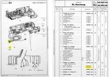
and for the plaque, here is the piece it is on. I also found it in the FW190 manual!
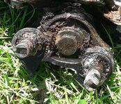
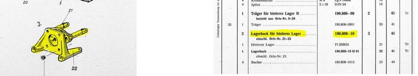
OK. IMHO that's the rear mounting for the machine guns used for Fw 190. These can be the MG 17, 131 or 151/20.
and for the plaque, here is the piece it is on. I also found it in the FW190 manual!
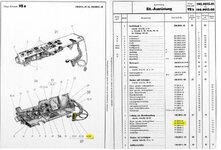
Please show the full pages of the parts lists to help. The 102-160 Gerat certainly looks like a gun mount.
Eng
OK. IMHO that's the rear mounting for the machine guns used for Fw 190. These can be the MG 17, 131 or 151/20.
Yes. Unfortunately, I don't have all the original info on the 190, but as the OP has some pics of the Ersatzteilliste, hopefully he could post them. I am leaning towards the top 131 fitting but I haven't got a Gerat number.
Eng
OK. IMHO that's the rear mounting for the machine guns used for Fw 190. These can be the MG 17, 131 or 151/20.
Definitely not MG 17, but likely rear rear fitting for one of the 131 or 151 mountings.
Eng
- Thread starter
- #38
perhaps the ammunition found can help identify the type of machine gunDefinitely not MG 17, but likely rear rear fitting for one of the 131 or 151 mountings.
Eng
Attachments
Snautzer01
Marshal
- 46,292
- Mar 26, 2007
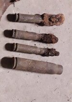
Can you get a ruler for dimensions in the pic?perhaps the ammunition found can help identify the type of machine gun
perhaps the ammunition found can help identify the type of machine gun
IMHO the smaller rounds seem to be of the MG 131 while the larger shell of the MG 151. But I agree with Snautzer , the measurement would be helpful.
Users who are viewing this thread
Total: 1 (members: 0, guests: 1)
Similar threads
- Replies
- 7
- Views
- 1K