Grumman HU-16B Albatross help needed (RCAF CSR-110 Albatross) (1 Viewer)

Ad: This forum contains affiliate links to products on Amazon and eBay. More information in Terms and rules

Colin L

Airman
43
95
Nov 27, 2016
I'm looking at converting the Trumpeter 1/48 HU-16A Albatross to an HU-16B (more specifically, an RCAF CSR-110).
I plan on using S2F cowls, engines and props for the correct powerplants, and 'bulging' the nacelles.
I'm aware of the wing and wingtip extensions, the larger span horizontal stab, and the taller tail, but I'm coming up short on some info ...
While the horizontal stab span was increased (with redesigned elevators), was the chord increased also, if so, by how much.
Also, the 'cuffed' leading edge to eliminate the slots in front of the aileron, how far out along the wing did it start?
Is there anything else I should be aware of?
DDGdteQW0AAL9ht.jpg


Thanks,
Colin
 
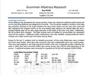
I have the Grumman SRM wing and horizontal stab station diagrams that show the increased span of both, but what they don't have is the chord of the stab, and the cross section of the wing showing the 'cuffed' leading edge and where it starts to curl down.
On this photo, it appears that the wing cross section at the nacelle is a 'standard' airfoil, but that the 'cuff' gradually increases towards the extended tip.
Image2.jpg
 
I have the Grumman SRM wing and horizontal stab station diagrams that show the increased span of both, but what they don't have is the chord of the stab, and the cross section of the wing showing the 'cuffed' leading edge and where it starts to curl down.
On this photo, it appears that the wing cross section at the nacelle is a 'standard' airfoil, but that the 'cuff' gradually increases towards the extended tip.
View attachment 721815
Beautiful shot.
 
I haven't found any info on the wing airfoils and the structure there. But in the pics below you may notice that the modified airfoil shape of the leading edge started from the engine nacelle and run towards the wing tip increasing at the aileron area.

wing3.jpg


wing2.jpg


wing4.jpg


wing6.jpg


wing5.jpg

the pic source: the net.
 
Excellent, thanks. That answers that!
It looks like the leading edge droop (cuff) starts at the nacelle, and becomes more pronounced as it moves outboard.
The third photo down also shows the cowling and nacelle bulge very well.
 
Yep, those are the SRM illustrations that I have. For the horizontal stab, they give the span, and the chord at the tip, but nothing on the chord at the root, where it attaches to the vertical stab. In the photos, it appears to be 6 to 12 inches longer there. On the Hull Station drawing sta.614 part way to sta.637 (dashed line for the HU-16B). Probably good enough to guesstimate, but if I make a resin conversion set, I'd like to be as accurate as possible.

Anyway, thanks for the info, it would be nice to have a conversion set for the Trumpeter kit, since they seem in no hurry to kit that version!
 
I see. Instead of making the resin conversion set you may try to find the RVHP no.48038 Grumman HU-16B Albatross 1/48 resin kit.

However I would say if the drawings on the scanned page 10 posted above are quite accurate you may get the tail dimensions in easy way. The vertical stabilizer had the 31' so the half of it is 15.5'. This dimension you have to divide by 48 to get the scale one. The same you get for the chord at the tip.... 46.271"/48. The next step is to print the scanned page at the A4 paper sheet keeping the proportion of the picture. Then measure the printed drwaing for getting the dimensions of the span and chord at the tip of the stabilizer in the pic. A then, dividing the span of the printed drawings by the needed dimension for the 1/48 scale you will get the ratio for enlarging or reducing of the scanned drwaings.
Personally I use the xerocopy device for that because it allows to enter the ratio in percents. So I use the formula for getting the dimension in percents ..

measured dimension from printed scan / needed dimension for a scale x 100% = ratio number in %

If the ratio number is more than 100% the drawing is resized down
if the ratio number is less than 100% the drawing is enlarged.
 
I've looked at the RVHP no.48038 Grumman HU-16B Albatross resin kit, and the problems there are you would still have to change the engines, props, cowl and nacelle, plus the only ones still available are on Ebay (vs. the widely available Trumpeter kit).
I've corresponded with the fellow on Ebay selling them and the kits he has have the short HU-16A wings! (he has photos and confirmed that is what is in the kit) Also, they appear to now have resin gear legs instead on the metal gear legs, and only one vac canopy instead of the original two.
 
It looks like the leading edge droop (cuff) starts at the nacelle, and becomes more pronounced as it moves outboard.
According to this page all versions of the Albatross had the same wing profile: NACA 23017 at wing root up to the wing tip.
That guy is collecting airfoil data - maybe he also can help out with the tail airfoils of horizontal and vertical stabilizer.
NACA 23017: camber position 15%, thickness 17%
On this page you can create the point clouds for the profiles. With the sketches posted here you have the corresponding wing depth at each position which is equal to the profile chord length. The percentages are calculated along the chord length.

The prominently visible droop on the wingtip has this reason:
The angle of attack of the wing profile at the wing root is generally designed to be about +1.5 to 3 deg (nose up relative to fuselage main axis, exact values depending on profile type).
The angle of attack of the wing profile at the wingtip is generally designed to be about -1.5 to 3 deg (nose down relative to fuselage main axis, exact values depending on profile type).
This considerable torsion of the profile along the wing span gives some essential benefits for flight behavior:
(1) take-off and steady flight: the wing creates constant lift at the wing root up to half the wingspan even with the aircraft rolling on ground with slight nose-down attitude.
(2) in flight, if you pull up the nose of the aircraft, the airflow will stall out first on the wing root reducing lift symmetrically, slowing down the aircraft climb, but the airflow on the wingtip remains attached to the profile thus keeping aileron effective and the aircraft under control.
With a straight wing, the airflow would detach from the wing profile at once over the full wingspan leaving the aircraft without lift from one moment to the next, and also uncontrollable as the ailerons would become useless. The aircraft would instantly drop and smear off over either one wing.
 
According to this page all versions of the Albatross had the same wing profile: NACA 23017 at wing root up to the wing tip.
That guy is collecting airfoil data - maybe he also can help out with the tail airfoils of horizontal and vertical stabilizer.
NACA 23017: camber position 15%, thickness 17%
On this page you can create the point clouds for the profiles. With the sketches posted here you have the corresponding wing depth at each position which is equal to the profile chord length. The percentages are calculated along the chord length.

The prominently visible droop on the wingtip has this reason:
The angle of attack of the wing profile at the wing root is generally designed to be about +1.5 to 3 deg (nose up relative to fuselage main axis, exact values depending on profile type).
The angle of attack of the wing profile at the wingtip is generally designed to be about -1.5 to 3 deg (nose down relative to fuselage main axis, exact values depending on profile type).

I don't think I can agree with this, Grumman redesigned the outboard wing with a leading edge 'cuff' or droop in order to eliminate the leading edge slot of the 'A' wing. The photos at the wing tip clearly show the drooped leading edge.
What you are describing is 'washout' - the twist or reduced angle of attack farther out the wing, to ensure a stall starts inboard, and the ailerons remain effective.
 

Attachments

  • wing.jpg
    wing.jpg
    368.9 KB · Views: 5
C Colin L , I have tired to find some more on the Albatross wing but nothing has been found so far. Looking at all gathered info I would say that the NACA 23017 is the correct base airfoil for the wing. Its shape of the leading edge at the engine nacelle indicates that for the both of the plane variants. The main difference was that the HU-16A wing had it at the wing root and its tip while the HU-16B had it at the wing root and at the end of the wing extension only. Then the airfoil was modified at the wing tip. If you would draw the intermediate airfoils from the end of the extension to the tip you would find the shape of the wing leading edge. The problem is the kind of the airfoil used at the wing tip. It might have been a modified NACA 23017 (23012) or other different airfoil of the cambered shape. Still looking for more info.
 
Let me start by saying I truly do appreciate your help with this, and I am only trying to be as accurate as possible.
Neither photos nor aerodynamics would support the idea that adding a drooped leading edge in the last 30" of the tip extension would help with stabilizing the airflow over the aileron. The slots it replaces are in front of the aileron to prevent the airflow from detaching at higher angle of attack (maintaining aileron effectiveness in the event of a stall situation). The extension starts at the outboard end of the aileron and a droop there alone would have no effect on airflow over the aileron.

The photo below clearly shows that the droop (cuff) farther down the wing in front of the aileron.

View: https://flic.kr/p/2oDcEY3

While the basic airfoil may remain unchanged, the drooped leading edge may well be an addition to the wing. That is the case with many STOL kit modifications. (that is why it is referred to as a 'cuff', it is added on to the leading edge)
 
All is fine Colin. You are right IMHO. However we might not understand each other. I thought you needed to find out the distance along the wing leading edge the cambered leading edge was. I made a diagram. Is that what you are looking for?

wing1.jpg
 

Users who are viewing this thread

Back