chris ballance
Airman 1st Class
- 151
- Jul 21, 2022
Did the British order the Hudsons and Venturas from Lockheed with self-sealing fuel tanks? Did the Lodestars ever get them?
Follow along with the video below to see how to install our site as a web app on your home screen.
Note: This feature may not be available in some browsers.
Ad: This forum contains affiliate links to products on Amazon and eBay. More information in Terms and rules
If there were self sealing tanks installed on any of the mentioned aircraft, that decision would come at the direction of the customer, be it the RAF, USN or USAAF.Just having internet references I'm assuming the Hudson Mk. IIIA, A-29, A-29A, PBO-1 was the long range version with the Wright R-1820-87. So it would have the additional wing tanks.
I was just interested in what fuel tank protection the Lockheed family of aircraft had given that they sometimes had tangle with aircraft and flak.
Petrol Tanks LeakingI bet that the Hudsons and Lodestars suffered from chronic fuel leaks from the wings. Any information on this subject?

 sillothairfield.wordpress.com
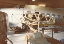
Excellent! Members take note here - this is real world restoration, I equate this to digging up dinosaur bones! Thanks for this post!!!!The illustration from the T.O. 01-75KA-2 is a tad misleading in that it conveys the impression that there are actual tanks per se. The description of a wet wing is best accurate.
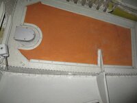
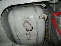
The inboard walls are the fuselage wall, the frontmost and rearmost walls are the front and rear shear beams of the wing, the outboard walls are the walls of the two bays of the nacelle, and the two in the centre between the two tanks are the faceplates of the box spar.
The rubber was applied to the outside of the vertical walls so that means it is inside the wing leading edge for example. It was often covered in fabric secured with metal edge beads but I've seen no evidence of anything being applied to the outside wing skin.
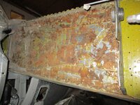
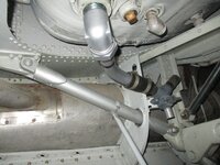
Here for example is the forward shear beam where in just the last couple of weeks I have been removing the remaining rubber, and the inboard wall of a wheel well bay.
Despite now being some 80 years old the rubber is still flexible and has a tenacious grip on the metal but there has been some corrosion occur so off it has to come!
")