This may be a little bit of a "dry" read, but I found it interesting...
If this is too hard to read...go to
FUEL TANK CONSTRUCTION
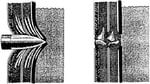
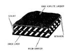
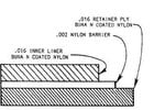
Self-Sealing Fuel Cells A self-sealing cell is a fuel container that auto- matically seals small holes or damage caused during combat operations. A self-sealing cell is not bulletproof, merely puncture sealing. As illustrated in figure 3-31, the bullet penetrates the outside wall of the cell, and the sticky, elastic sealing material surrounds the bullet. As the bullet passes through the cell wall into the cell, the sealant springs together quickly and closes the hole. Now some of the fuel in the tank comes in contact with the sealant and makes it swell, completing the seal. In this application, the natural stickiness of rubber and the basic qualities of rubber and petroleum seal the hole. This sealing action reduces the tire hazard brought aboutby leaking fuel. It keeps the aircraft's fuel intact so the aircraft may continue operating and return to its base. The most commonly used types of self-sealing fuel cells are the standard construction type and the type that uses a bladder along with the self-sealing cell. Of the two, the standard construction cell is used the most. It is a semiflexible cell, made up of numerous plies of material. The combination bladder and self-sealing cell is made up of two parts. One part is a bladder-type cell, and the other part is identical to the standard construction cell. It is designed to self-seal holes or damage in the bottom and the lower portions of the side areas. The bladder part of the cell (nonself-sealing) is usually restricted to the upper portion. This type of cell is also semi flexible. SELF-SEALING CELL (STANDARD CONSTRUCTION).— There are four primary layers of materials used in the construction of a self-sealing cell. These layers are the inner liner, nylon fuel barrier, sealant, and retainer. All self-sealing fuel cells now in service contain these four primary layers of materials. If additional plies are used in the construction of the cell, they will be related to one of the primary plies. The inner liner material is the material used inside the cell. It is constructed of Buna N synthetic rubber. Its purpose is to contain the fuel and prevent it from coming in contact with the sealant. This will prevent premature swelling or deterioration of the sealant. Buna rubber is an artificial substitute for crude or natural rubber. It is produced from butadiene and sodium, and is made in two types, Buna S and Buna N. The Buna S is the most common type of synthetic rubber. It is unsuitable for use as inner liner material in fuel cells. It causes the petroleum fuels used in aircraft to swell and eventually dissolve. The Buna N is not affected by petroleum fuels, making it ideal for this application. However, the Buna N is slightly porous, making it necessary to use a nylon barrier to prevent the fuel from contacting the sealant. The nylon fuel barrier is an unbroken film of nylon. The purpose of the nylon fuel barrier is to prevent the fuel from diffusing farther into the cell. The nylon is brushed, swabbed, or sprayed in three or four hot coats to the outer surface of the inner liner during construction. The sealant material is the next material used in fuel cell construction. It remains dormant in the fuel cell until the cell is ruptured or penetrated by a projectile. It is the function of the sealant to seal the ruptured area. This will keep the fuel from flowing through to the exterior of the fuel cell (fig. 3-31.) The mechanical reaction results because rubber, both natural and synthetic, will "give" under the shock of impact. This will limit damage to a small hole in the fuel cell. The fuel cell materials will allow the projectile to enter or leave the cell, and then the materials will return to their original position. This mechanical reaction is almost instantaneous. The chemical reaction takes place as soon as fuel vapors penetrate through the inner liner material and reach the sealant. The sealant, upon contact with fuel vapors, will extend or swell to several times its normal size. This effectively closes the rupture and prevents the fuel from escaping. The sealant is made from natural gum rubber.The retainer material is the next material used in fuel cell construction. The purpose of the retainer is to provide strength and support. It also increases the efficiency of the mechanical action by returning the fuel cell to its original shape when punctured. It is made of cotton or nylon cord fabric impregnated with Buna N rubber. SELF-SEALING CELL (NONSTANDARD CONSTRUCTION).—One variation from the standard construction, self-sealing fuel cell previously discussed is shown in figure 3-32. It has four primary layers–an inner liner, a nylon fuel barrier, two sealant plies, and three retainer plies. The cords in the first retainer ply run lengthwise of the cell. The cords in the second retainer run at a 45-degree angle to the first. The cords in the third retainer run at a 90-degree angle to the second. The outside is coated with Buns-Vinylite lacquer to protect the cell from spilled fuel and weathering. Baffles and internal bulkheads are used inside the cell to help retain the shape of the cell and prevent sloshing of the fuel. They are constructed of square woven fabric impregnated with Buna N rubber. Flapper valves are fitted to some baffles to control the direction of fuel flow between compartments or interconnecting cells. They are constructed of Micarta, Bakelite, or aluminum. These plies, baffles, internal bulkheads, and flapper valves with the necessary fittings and combinations make up a typical self-sealing fuel cell. A nonself-sealing fuel cell is commonly called a bladder cell. It is a fuel container that does not self-seal holes or punctures. The advantage of using a bladder fuel cell results from the saving in weight. Some of the other advantages are the simplicity of repair techniques and the reduced procurement costs over self-sealing fuel cells. Bladder-type cells are usually made of very thin material to give minimum possible weight. They require 100-percent support from a smooth cavity. The cell is made slightly larger than the cavity of the aircraft for better weight and distribution throughout the aircraft's fuel cavity structure. The thinner wall construction increases the fuel capacity over the self-sealing cells, thus increasing the range of the aircraft. Many of our aircraft that were formerly equipped with self-sealing cells have been changed to bladder-type cells. There are two types of bladder fuel cells–rubber type and nylon type. RUBBER-TYPE BLADDER CELLS.—The rubber-type bladder cells are made in the same manner as self-sealing cells. They have a liner, nylon barrier, and a retainer ply. The sealant layers are omitted. All three plies are placed on the building form as one material in the following order: liner, barrier, and retainer. Figure 3-33 shows this type construction. The inner liner may consist of Buns N rubber, Buna N coated square-woven fabric (cotton or nylon), or Buna N coated cord fabric. The purpose of the inner liner is to contain the fuel and provide protection for the nylon barrierThe nylon barrier consists of three to four coats of nylon applied hot by brush, swab, or spray. The purpose of the nylon barrier is to keep fuel from diffusing through the cell wall. The retainer consists of Buna N coated square- woven fabric (cotton or nylon) or cord fabric. The purpose of the retainer ply or plies is to lend strength to the fuel cell and provide protection for the nylon fuel barrier. NYLON-TYPE BLADDER CELLS (PLIO- CEL).—Nylon bladder cells differ in construction and material from the Buna N rubber cells. This type of cell may be identified by the trade name "Pliocel" stenciled on the outside of the cell. The Pliocel construction consists of two layers of nylon woven fabric laminated with three layers of transparent nylon film. The repair of this type of cell must be accomplished by entirely different methods and with different materials. The adhesive and Buna N rubber used to repair the rubber-type bladder cell cannot be used on the nylon-type cell.
The illustrations below are 3-31, 32 and 33


 ) and a fast acting automatic system might be beyond WW II capabilities.