Mosquito Fb VI crew oxygen, hydraulic, pneumatic and control cable information

Ad: This forum contains affiliate links to products on Amazon and eBay. More information in Terms and rules

Mrmavx

Recruit
4
2
Dec 31, 2025
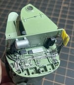
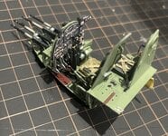
Hello all I am currently building a tamiya 1/32 mosquito fb vi I am trying to add as much detail as possible but I'm finding pictures/information difficult to find on the cable and pipe runs down each side of the bomb bay and the area behind crew armour and front of wing spar if anyone can help it would be greatly appreciated. I have good pictures of the front and rear wall of bomb bay but nothing in between ( pic1 is bay front wall I'm using ) I'm also trying to find the oxygen hose runs from the economisers? Into the cockpit.
Pic2 and 3 are my progress with the model
 

Attachments

  • att.chjAIh_b-nsg_W2c5yCN8DuBJRZSqGi3T2L1l3pYHMM.jpeg
    att.chjAIh_b-nsg_W2c5yCN8DuBJRZSqGi3T2L1l3pYHMM.jpeg
    235.1 KB · Views: 30
  • IMG_8831.jpeg
    IMG_8831.jpeg
    292.8 KB · Views: 31
  • IMG_8886.jpeg
    IMG_8886.jpeg
    679.2 KB · Views: 36
Last edited:
Welcome aboard. That's some really nice work you are doing so far. I'll post here some pictures I took of restored KA114 in 2014 though the details you are looking for may be hard to discern.

IMG_5269 Posted.jpg
IMG_5270 Posted.jpg
IMG_5271 Posted.jpg
IMG_5291 Posted.jpg


Here are some excerpts from various manuals I have that might help you:

1772398697894.png
1772398776982.png


Oxygen System. I believe that the economizers are on the roof of the bomb bay just forward of the front wing spar. The tubing is 1/4" copper. Feed comes from the bottles in the rear along the starboard side of the fuselage above the wing then down behind the Nav armour plate, piercing the roof of the bomb bay on the stbd side. I'm not very familiar with the run of the hoses from the economizers to the users, though the diagram below shows a long loop for the Nav and a short length for the pilot. The British manual diagrams are very hard to follow, in my opinion. The Canadian and Aussie ones are better, but the oxygen systems for the FB.26 and 40 will be quite different form yours.

1772399109297.png


The area behind the armour plate is a mess. The main things that you'll see are 3 torque tubes: throttle, prop pitch, and mixture. There are also fuel cocks with slow running cut-out switches that operate chains and cables running along the front spar to each engine. Tubing will consist of fuel tank venting, oil dilution, and pressure lines from engine vacuum pumps to the drop tanks via controls next to the Nav. The diagram below might help. It shows the wing detached from the fuselage. The "Area A" called out in this diagram refers to the Area A detail in the first diagram I posted above.

1772399858429.png


I don't have any photos of this area for an F.B. VI but lots for a B.35 which has some differences. Happy to help with specifics if you need them as it's a lot of detail for this post. I've been quite involved in these areas on a B.35 restoration and can lead you down the deepest rabbit hole you dare to go, depending on how much detail you want to show. My 1/48 F.B. VI build might also help with other points, though I've not addressed all the details that a 1/32 kit would warrant.

 
Crimea_River
Many thanks for your post and the information/pictures, they will most definitely help with the detail I am going to add to my build especially the drawings of the aileron cables and the pulley which I new existed but didn't know which and how many cables ran thru it, the sidewall drawing is also a great help and 1 I had never seen before. If you have any more drawings of any parts of the bomb bay and its walls they would come in very handy. I haven't got all the way thru your 48 FB VI build thread but will do soon the stuff about the gee units is quite interesting and helpful as well.
 
I get a big kick out posts that ask questions about the Mosquito.
"I'm trying to determine the correct installation of the left handed poop-shank on the Mosquito's starboard frabilizer for a model I'm building."
"Half a mo'. I'll step out back and take a few snaps."
 
Crimea_River
Many thanks for your post and the information/pictures, they will most definitely help with the detail I am going to add to my build especially the drawings of the aileron cables and the pulley which I new existed but didn't know which and how many cables ran thru it, the sidewall drawing is also a great help and 1 I had never seen before. If you have any more drawings of any parts of the bomb bay and its walls they would come in very handy. I haven't got all the way thru your 48 FB VI build thread but will do soon the stuff about the gee units is quite interesting and helpful as well.
A few more figures:

1772637869923.png


From Canadian-built FB26 manual which should be similar:

1772638726239.png
1772638914049.png
1772639439719.png


Hydraulics:

1772639651317.png
 

Users who are viewing this thread

Back