MACHIA
Airman
The P-40 did not use the Meridith effect in its design ? It's a high drag airplane , so was wondering if it's air scoop had anything to do with that .
Follow along with the video below to see how to install our site as a web app on your home screen.
Note: This feature may not be available in some browsers.
Ad: This forum contains affiliate links to products on Amazon and eBay. More information in Terms and rules
The P-40 did not use the Meridith effect in its design ? It's a high drag airplane , so was wondering if it's air scoop had anything to do with that .
The P-40 did not use the Meridith effect in its design ? It's a high drag airplane , so was wondering if it's air scoop had anything to do with that .
I wish people would read the various GB patents held by TP de Paravicini. He covered the negative drag in various patents including air cooled radial engines.Was there any Merideth effect in the P-40 design ? I doubt it highly as the P-40 inlet was considered high drag. Thought I'd ask though. Perhaps someone may know if it was at least attempted. I do know that the prototype had a mounting similar to the P-51 before it was moved forward.
The Meredith effect produces thrust from the heat of the engine. The idea is to reduce the overall cooling drag, I suppose it is possible to have a lot of "Meredith effect" but still have massive cooling drag because of the inlet and other "stuff". In principle, by description, there is little difference between the arrangement on a Hurricane and a P-51, in practice the difference is huge.Was there any Merideth effect in the P-40 design ? I doubt it highly as the P-40 inlet was considered high drag. Thought I'd ask though. Perhaps someone may know if it was at least attempted. I do know that the prototype had a mounting similar to the P-51 before it was moved forward.
You can patent the idea or the formulas and attach drawings to illustrate the idea. It doesn't mean that something built to those drawings is actually going to work.
I am not trying to take anything away from TP de Paravicini. His drawings may have worked. However there was a lack of actual experimentation/ test back up at the time.
I believe the British only got a 24 ft wind tunnel into operation in 1935/36? You might be able to squeeze a bipane into it with the wing tips cut off. I have no idea how fast the airflow was.
Remember it was the guys running this wind tunnel that thought (or provided the formulas to the airframe makers) that the Beaufighter I was good for 370mph and the early Typhoon should have gone 460mph.
Lets just say that practical experience was years behind the theory.
We also have to forget the idea that any and all radiators placed on the belly of an airplane were somehow using the Meredith effect just because the Mustang had a radiator on/in the belly and did use the meridieth effect.
The XP-40 with the belly radiator had trouble breaking 300mph so obviously the under nose radiator set-up was better. Still doesn't mean it used the Meredith effect, or used it to any real benefit.
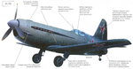
With the P-40 you had 4 or more different nose radiator setups. the XP-40 went through more than one(?), the P-40/P-40B/P-40C used another. the P-40D/E and later Allisons used the 3rd and the P-40F & L used 4th.
This is complicated by the fact that the P-40 used some different Allisons with different power ratings and used the Merlin which had different radiator/oil cooler requirements than the Allisons. These different engines affect the cooling airflow requirements and thus the size of the radiator/oil cooler inlet and/or outlet. Once you get passed the XP-40 the long nose planes used a 1040hp engine (if it wasn't being abused) while the D & E got a 1150hp engine. I have no idea how much larger the radiators got if they got any bigger.
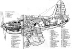
View attachment 538400
Upper picture ins the long nose P-40, lower ones are the radiators/oil cooler in the later Allison models. There is little or no expansion of the airflow before it hits the radiators.
rear view of the radiators
View attachment 538401Photo credited to Scott Murphy.
It is a museum plane and while the outlet is adjustable the actual airflow in the "duct" is short and has some sharp corners to get around. Not a lot of expansion space.
when they changed to the D & E you got this
View attachment 538402
Please note the centerline of the prop moved up 6 inches and the prop moved back. I don't know if they lowered the bottom of the radiator cowl any but the inlet opening was sure raised at the top.
The P-40F used a Merlin rated at 1300hp and used a bigger radiator and two oil coolers, It did drop the radiator inlet opening.
Late model P-40s used engines rated for 1200hp and were officially rated for WER power levels.
How much the later/higher powered engines also impacted the need for a longer tail I don't know.
Bottlehead replies. There are numerous patents that TP de Paravicini alone or with his boss at Rolls Royce Edwin Ellor filed that covered various methods of
cooling by means of utilizing waste heat. TP de Paravicini was at Farnborough research prior to being recruited to Rolls Royce.
It appears the Americans latched on to Meridith. His patent is preceded.
Rolls-Royce Crecy engine which was to be installed in Spitfire
.
I believe the British only got a 24 ft wind tunnel into operation in 1935/36? You might be able to squeeze a bipane into it with the wing tips cut off. I have no idea how fast the airflow was.
Remember it was the guys running this wind tunnel that thought (or provided the formulas to the airframe makers) that the Beaufighter I was good for 370mph and the early Typhoon should have gone 460mph.
Lets just say that practical experience was years behind the theory.
We also have to forget the idea that any and all radiators placed on the belly of an airplane were somehow using the Meredith effect just because the Mustang had a radiator on/in the belly and did use the meridieth effect.
When were these ejectors added?His theory was born out in practice by the increased speeds achieved in the Spitfire coupled with his exhaust ejectors overall added about 50 mph.
Rolls Royce cross licensed many patents with the Germans prior to WW2 and that is how the ME109 got the same cooling arrangement as well as being offered the Merlin engine design.
I get an efficient inlet, an efficient nozzle, the highest reasonable temperature differential between radiator air: What I don't get is a minimal pressure change at the radiator. I'd figure you'd want the heat to rapidly heat and cause a maximum pressure change.It would require an efficient inlet, to slow the air, a minimal air pressure drop in the radiator, and an efficient nozzle. Having the highest possible temperature in the radiator would also help.
Yeah, you'd need to adjust the nozzle to deal with the airflow changes through the duct.to add to that the exit nozzle/area, needs to be variable in area in small steps, A fixed exit or two position exit is only going to be efficient an certain airspeeds and air densities.
That's why he left Curtiss? Over the inability to design the radiators how he wanted?The designer of the P-40, Berliner, claimed that the longer tail on the P-40 was required due to the front of the radiator being too large, which caused excess air to spill out of the front and flow back along the fuselage. He considered the fuselage length extension to be a crude way to handle the problem, when redesigning the air scoop would have been better. He left Curtiss over such issues.
Looking at the P-40F
View attachment 573550
While the basic shape seems good, it seems that the basic problem is that there's no splitter to remove turbulent airflow from the duct. It was highly important that the airflow into the duct be smooth. I remember that in a book I read on the Spitfire (and it was a problem in the Spitfire).