wuzak
Captain
Is that the XP-40F?
Looks like the XP-60, but with P-40 wings and undercarriage.
Follow along with the video below to see how to install our site as a web app on your home screen.
Note: This feature may not be available in some browsers.
Ad: This forum contains affiliate links to products on Amazon and eBay. More information in Terms and rules
What kind of cowling would you need for a radial to make use of the Meredith effect to good degree?
Very, very, very well designedA well-designed NACA cowling.
")
Very, very, very well designed
It'd look good if it had a splitter...How comes that basic shape seems good?
Hawkers experimented with a set up like that for the Typhoon/Tornado but stuck with the chin radiator.It'd look good if it had a splitter...
It'd look good if it had a splitter...
It would require an elaborate bell-mouth shape. The problem would be ensuring adequate cooling while keeping drag low.Very, very, very well designed
You might very well be right.Disagree...
Hawkers experimented with a set up like that for the Typhoon/Tornado but stuck with the chin radiator.
It would require an elaborate bell-mouth shape. The problem would be ensuring adequate cooling while keeping drag low.
Maybe not exclusively about aerodynamics it takes the place where a bomb or tank goes.Tornado was originally designed that way, but quickly changed to the chin radiator.
I've seen it that the Typhoon was always to have a chine radiator and also that the chin radiator was adopted after initial flights of the Tornado.
The Typhoon's first flight was several months after the Tornado's, which makes the latter possible.
The former is also possible, but I struggle to believe that Hawker would design two nearly identical airframes with two different cooling systems.
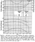
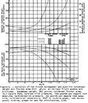
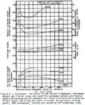
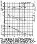
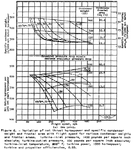
Where the airflow into them is nice and high.In actuality many/most of the WW II radial engine fighters had more cooling intake area than they needed for high speed flight.
How would one have gotten around that problem?The problem/s were insuring adequate air flow on the ground or in a long climb.
I'm guessing slowing it down too much would mean it wouldn't have enough speed to flow over the cylinders effectively, and carry away the heat in the process?Problems in getting the Meredith effect to work on air cooled engines are;
1. not slowing the airflow down too much as it goes through the cowl/baffles/fins. Some slow down is beneficial as the lower speed airstream will have lower drag going though the labyrinth of baffles.
How would one have avoided this problem?2, not introducing too much turbulence as it does so.
So you'd want the space behind the cylinders to be of convergent design, thus allow the airflow to accelerate, but long enough to ensure the airflow smooths out after flowing over the cylinders, while not being too long, as to produce losses?3. having adequate space behind the cylinders to smooth the airflow and compress it as it approaches the exit/s without introducing any(much) turbulence.
4 having outlets of proper size to get the exit speed of the cooling air up to the required speed.
The cooling-air outlets are located in the rear part off the cowling, behind the cylinders, correct?5, having the cooling air outlets somewhat aligned with the direction of travel without creating drag.
I'm curious about the gill arrangement seen in the Tempest Mk.II. How hard that kind of set-up to work? It looked very aerodynamic, as it didn't protrude into the wind like general cowl-flaps.6. having to deal with real world problems.
How would one have avoided this problem?.
I'm curious about the gill arrangement seen in the Tempest Mk.II. How hard that kind of set-up to work? It looked very aerodynamic, as it didn't protrude into the wind like general cowl-flaps.
His name was indeed Thomas Pitt de Paravicini.TP de Paravicini. Or Thomas Pitt de Paravicini.
TP de Paravicini. Or Thomas Pitt de Paravicini.
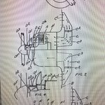
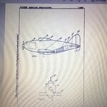
Original patentView attachment 574159I realize that, because the powerplant used in it was very similar to the Rolls Royce Goshawk, which was also an evaporatively cooled engine. And look at how successful that was. I'm not sure, but did the Germans try this on other aircraft, other than the He100 fighter? The British used this on a number of flying machines built, and was also proposed for such designs as RJ Mitchell's design for the Type 232, his contribution being a gull winged four engine patrol flying boat of the Sundeland class. In this case, the intake for the condensers being the entire leading edge of the wings.
My thought is if something similar to the belly scoop on the P51(as well as the MB5 and the Australian Mustang lookalike, but not scoop shaped, but one with an equal amount of area, could be doable.
I'm not sure if the Germans were even aware of the Meredith Effect, even though at the time of the 119m they might've had more than a few Mustangs brought down that they might have studied. I dunno, but if they weren't(and I have yet to learn that they did know of it, if only by dint of studying the Mustand cooling system in toto), wouldn't something like this be useful now, given advancement in materials technology since the War? I'm speaking as as mechanic who has been doing too much thinking. so perhaps I'm sorely mistaken in my assumptions. Still, it might be something worth consideration, 'cause an engine that can dissipate engine waste heat at a higher rater due to higher temp/ambient temp differential.
This is what I get for being the kind of person who thinks a few miles outside the litter pan.
Patent filed 1936 by TP de Paravicini. Mustang is similar but later. So used this basic patent.I realize that, because the powerplant used in it was very similar to the Rolls Royce Goshawk, which was also an evaporatively cooled engine. And look at how successful that was. I'm not sure, but did the Germans try this on other aircraft, other than the He100 fighter? The British used this on a number of flying machines built, and was also proposed for such designs as RJ Mitchell's design for the Type 232, his contribution being a gull winged four engine patrol flying boat of the Sundeland class. In this case, the intake for the condensers being the entire leading edge of the wings.
My thought is if something similar to the belly scoop on the P51(as well as the MB5 and the Australian Mustang lookalike, but not scoop shaped, but one with an equal amount of area, could be doable.
I'm not sure if the Germans were even aware of the Meredith Effect, even though at the time of the 119m they might've had more than a few Mustangs brought down that they might have studied. I dunno, but if they weren't(and I have yet to learn that they did know of it, if only by dint of studying the Mustand cooling system in toto), wouldn't something like this be useful now, given advancement in materials technology since the War? I'm speaking as as mechanic who has been doing too much thinking. so perhaps I'm sorely mistaken in my assumptions. Still, it might be something worth consideration, 'cause an engine that can dissipate engine waste heat at a higher rater due to higher temp/ambient temp differential.
This is what I get for being the kind of person who thinks a few miles outside the litter pan.
His name was indeed Thomas Pitt de Paravicini.
But for patents the name filed is just TP de Paravicini.
Another pic from another patent
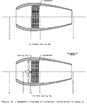
The wing inlets that TP de Paravicini showed in severalWhere does the bold in your post come from with regard to me? The Meredith effect is quite easy to explain much harder to do effectively. The Spitfire used it but not very well. The inlet was on the wing surface and had problems with the boundary layer, the outlet was also poor. Despite this Supermarine kept it as it was, even on the successors to the Spitfire. Hawkers tried a cooling system with the inlet under the fuselage on the Typhoon/Tempest but reverted to the chin type, it isn't easy to change things about once a design is made.