Many thanks for the prompt reply.
Nice kit indeed greetings.
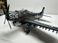
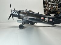
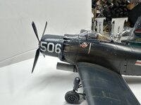
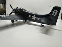
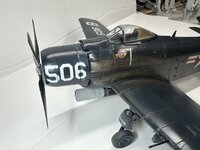
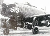
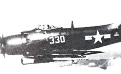
I see you have re created the VA-195 crest by paint as (it seems impossible) no one has ever print it on a decal. The new 1/72 AD-4 (finally!) Sword kit that I owe has in its decals a VA-195 Aircraft but the "509" as in a famous picture of (I suppose of the 1952) with plenty of bombs. Witout this crest anyway. So I think I'll have to try to print a decal of my own, or paint in some way.
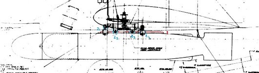
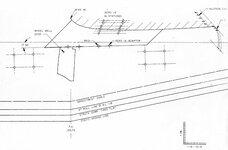
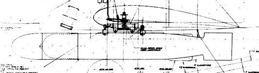
I include the drawing given me for kind concession of the National Naval Aviation Museum that i conctated (they made me have, very kindly indeed all the picts I'm going to attach).
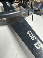
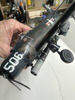
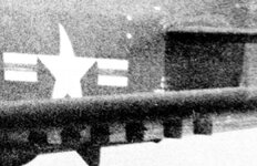
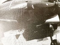
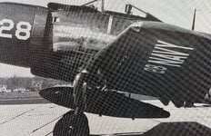
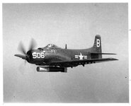
I have a question about the Serial Nr I see: 123771. have you found some proof about? Trying to magnifying the "506" pict is impossible to read (2nd pict attached) even if it's a crop from the high resolution picture.
Forgotten Props - A Warbirds Resource Group Site give me as beloging to VA-75 as L-515 in 1952
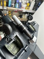
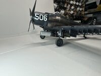
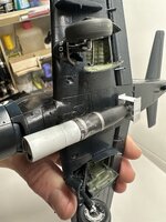
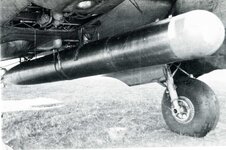
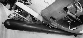
Speaking about the Torpedo Rack I've double checked all the drawings and images I obtained or found and i've arrived to a finding. I'm not fully sure of it because all the picts are very difficoult to read in someway, but I guess it rather plausible missing the definitive proof. If someone had the
AD-4 Skyraider Erection & Maintenance Pilot's Handbook Flight Manual most probably there would be the answer to how to mount the torpedo (now a bid on ebay but the seller ship in the USA only...)
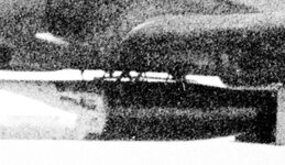
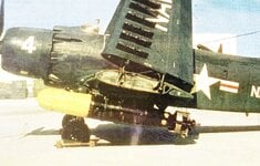
The starting point it a magnification of the Hi res quality pict of the 506 (by the way the original caption of the pict sent me by museum attributes it to the Lt Cmdr Carlson, where for others the Carlson aircraft was the 501...:
AD-4 Skyraider BuNo123827, VA-195 Dambusters, 1950s
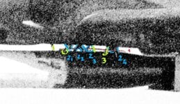
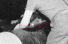
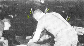
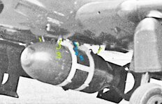
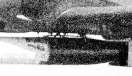
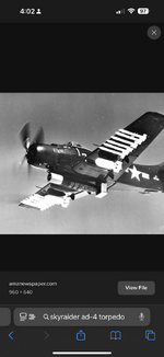
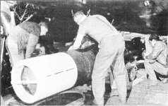
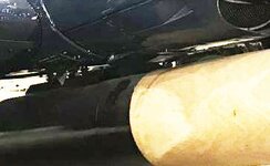
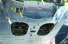
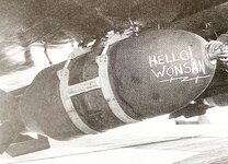
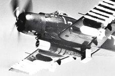
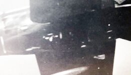
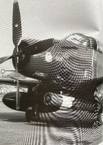
Checking with other images I've found that probably the mount was composed by four positioning braces (ref 3 in green), two for side; 4 alligned pins (ref 2 in azure) used as spacing between the aircraft belly, and the top of the torpedo; most probably almost one of them (the 2-3 for the bell shape?) was containing an explosive cartridge in order to eject the bomb in case of dive bombing, but Sanderson in its article of 2004 that Museum sent me, says that they feared that this little explosion could damage Torpedo or the fall of it anyway, so they operate all by hand. The pictures evidence a sort of thin plate or membrane or web or... (?) that runs parallel to aircraft belly and the upper surface of the torpedo, jus in the middle of the space between them. No idea what it was, but it seem it was there. In the pictures I've found no trace of the large bands you used to retain the torpedo. There is evidence of them in the picture of the bomb, but in was a bomb not a Torpedo and they are hightly visible there. On the aircraft carrying the torpedo picture there isn't trace of them. The question of how an heavy torpedo could be retained is still unanswered, but maybe it's right the thin plate (or web?) a trace for the solution. Anyway if I serach how the torpedo were usually retained in the 2 WW usually were tight to the rack by two wires (in the Douglas TBD Devastator wires were tied to a hole with a wire cutter in the two bomb racks running parallel on the two sides to the frontal part of the bomb bay; In the Savoia Marchetti SM 79 a famous Italian Torpedo Bomber the same; but AD-4 hasn't the two racks with the wire cutter) so I'm expecting the holes with the wire cutter were somewere in the belly, or maybe just in the rack embedded in the fuselage. Anyway in the pict no trace of wires also, but thin wires in a not sharp picture could be almost unvisible