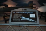
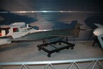
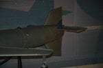
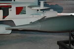
It looks much more like a V-1 wing.
Navigation
Install the app
How to install the app on iOS
Follow along with the video below to see how to install our site as a web app on your home screen.
Note: This feature may not be available in some browsers.
More options
You are using an out of date browser. It may not display this or other websites correctly.
You should upgrade or use an alternative browser.
You should upgrade or use an alternative browser.
Unknown german ww2 wing. Aircraft? Flying bomb? Rocket?
- Thread starter Truffle Pig
- Start date
Ad: This forum contains affiliate links to products on Amazon and eBay. More information in Terms and rules
More options
Who Replied?At 1 meter span though it is too small for a V1.
This is really interesting.
This is really interesting.
Heerbrandt Werke A.G. in Raguhn was manufacturing parts for Junkers. Did Junkers deliver parts to other companies?
Could this part be a fairing of something, like radio mast? Something to be mounted vertically or under an angle? Aren't all wing profiles asymmetrical (to a horizontal axis), to create lift?
Could this part be a fairing of something, like radio mast? Something to be mounted vertically or under an angle? Aren't all wing profiles asymmetrical (to a horizontal axis), to create lift?
Dessau is where Junkers Flugzeugwerk was located.
I would start looking at Junkers designs. Could it be a part from a smaller to scale mock-up?
I would start looking at Junkers designs. Could it be a part from a smaller to scale mock-up?
Raguhn was a supplier of parts to Junkers but it wasn't established until sometime in 1943, so if this piece was built there, then it had to be for one of the aircraft Junkers was still building by then. This is ringing a faint bell somewhere in my memory but I can't quite retrieve the thought. If it weren't for the 4 sets of 2 holes on both upper and lower surfaces, I'd have been strongly tempted to think it was a segment of a dive brake or flap like Junkers put on so many of their aircraft, very much like the inboard segment on the Ju-87 for example. But those holes, and the faint traces of some sort of fairing or something around them, don't fit with that at all. Apart from Me-163 and 263, and other things that Raguhn may have been involved with, the major things Junkers was working on in 1943-45 don't seem to line up here. I love a good mystery like this and I'll be fascinated to see what the final outcome is. In the meantime, for a good discussion on what was going on at Raguhn, CIOS Evaluation Report No. 149 is a good resource, and it's available on Google Books to read online. In the meantime, this seems to be a good list of Junkers' mainstream projects although it doesn't split things out by dispersed site source.

Just a small addition: AFAIK there were more factories/plants in Raguhn manufacturing for Junkers. The one in question is Heerbrandt-Werke A.G. The name of the factory was in fact changed to the latter one in 1943 when they became Junkers supplier.Raguhn was a supplier of parts to Junkers but it wasn't established until sometime in 1943....
Last edited:
Could it just be a production example? Like, look what we have the capability to do, and that's why it has the manufacturers name on it?
warbooklover
Airman
Does the span match up?
GrauGeist
Generalfeldmarschall zur Luftschiff Abteilung
Looks just about dead-on. The horizontal stabilizers on the Hs117 were like a modern fighter, where the entire assembly moves (instead of having an elevator).Does the span match up?
Also, Heerbrandt (in Ragau) was a sub-contractor to Junkers, meaning they would have had contracts to other companies (like Henschel) as well.
I think warbooklover nailed it.
These photos are on-line, but the Main web page no longer exists. https://www.deutscheluftwaffe.com/a...s 117 Schmetterling/hs 117 schmetterling.html
Appears to show movable trim tabs for wing & elevators.
https://www.deutscheluftwaffe.com/a...17 Schmetterling/Skizzen/Tafeln Gross/001.jpg
https://www.deutscheluftwaffe.com/a...17 Schmetterling/Skizzen/Tafeln Gross/004.jpg
https://www.deutscheluftwaffe.com/a...17 Schmetterling/Skizzen/Tafeln Gross/005.jpg
WW2 Equipment Data: German Explosive Ordnance - Rockets (Part 2)
MiTasol
Captain
I thought the V-1 was bigger but that is just my impression.
Attached is the V-1 Parts Catalog. The part numbers look wrong but I can not read German so that again may be my error.
More specifically the manual shows attachment hardware holding the wing to the spar and there is no evidence of those fittings in Truffle Pigs photos so I would say it is not a V-1 wing. And the tail is totally different.

Back to square one for a few minutes or days
Attached is the V-1 Parts Catalog. The part numbers look wrong but I can not read German so that again may be my error.
More specifically the manual shows attachment hardware holding the wing to the spar and there is no evidence of those fittings in Truffle Pigs photos so I would say it is not a V-1 wing. And the tail is totally different.
Back to square one for a few minutes or days
Attachments
MiTasol
Captain
Looking at the total lack of attach provisions I am going to go out on a limb and suggest that the eight through bolts are slacked off while the unit is slipped on then retorqued and the resulting clamping action keeps it in place.
- Thread starter
- #34
Truffle Pig
Airman
Looking at the total lack of attach provisions I am going to go out on a limb and suggest that the eight through bolts are slacked off while the unit is slipped on then retorqued and the resulting clamping action keeps it in place.
Good morning in 2021!
I like the discussion here very much.
MiTasol described exact how the part has been fixed to a tube: by pressing with the help of these eight screws. Unfortunately I am not able to open the screws, because I do not want to demolish that object. But if I could, I think I would separate both half. That makes the production (riveting) more easy.
Here three new pics to get a better impression.
Both half are only connected by the 8 screws. Not connected by rivets as you can see here.
Can't be right. The V-1 didn't use Aluminum in the wings, all steel except a late production series utilising wood.My guess is the V-1. It has a tubular spar and the shape looks correct.
Could be for a prototype missile or maybe one of JUNKERS pulse-jet powered manned interceptor prototypes.
skyskooter
Airman
- 33
- Jul 8, 2016
My money is on the tail surfaces of the Schmetterling missile. If so this is a remarkable find.
Does the span match up?
According to wiki, the main wing span is 2 metres.
According to Nowarra, the tail span is 1 metre.
This is a small missile.
If that's the case then each fin must be less than 50 cm as they are connected to each side of the rear fuselage?
Is it my eyes or are there control surfaces just visible on the port rear fin?
Looking closer...
Where the fin attaches to the rear fuselage - it would be tapered? The leading edge would be shorter than the trailing edge. This isn't seen in Truffles photos.
Last edited:
According to wiki, the main wing span is 2 metres.
According to Nowarra, the tail span is 1 metre.
This is a small missile.
If that's the case then each fin must be less than 50 cm as they are connected to each side of the rear fuselage?
Is it my eyes or are there control surfaces just visible on the port rear fin?
View attachment 606959
Looking closer...
Where the fin attaches to the rear fuselage - it would be tapered? The leading edge would be shorter than the trailing edge. This isn't seen in Truffles photos.
View attachment 606970
The drawings in Post #31 will answer your questions.
skyskooter
Airman
- 33
- Jul 8, 2016
I cannot access the first four of the links in Post # 31 but only the fifth. From the drawing it is apparent that there are control spoilers on the trailing edge of the tail surfaces (in common with the wings and fin) which are absent from the object under discussion. However they could conceivably be an addition. The text describes the structure of the flying surfaces as cast magnesium sheeted in aluminium. That is a positive but the span is wrong.
IMHO it can't because it needs cut-outs in the trailing edge. This trim-tab (Ruderleiste) is 635mm long and moves obviously in and out. There should be 3 cut-outs in this position.I cannot access the first four of the links in Post # 31 but only the fifth. From the drawing it is apparent that there are control spoilers on the trailing edge of the tail surfaces (in common with the wings and fin) which are absent from the object under discussion. However they could conceivably be an addition. ....
On the other hand the structure (framing) in the drawing looks completely different compared to the pictures. For example there are 3 small openings in the first rib (represented with dashed lines) and 2 in each of the other ribs but none on the picture. The ribs do not end at the trailing edge but good 70-80mm before it etc.
Look at the edge of the apparent wing: it has a flange (where it meets the fuselage, body etc.) but the flange is only slightly scratched. If this is a moving part this wouldn't be the case. It wouldn't be designed in this way at all.
Cheers!
Happy New Year!
Last edited:
Users who are viewing this thread
Total: 1 (members: 0, guests: 1)
Similar threads
- Replies
- 10
- Views
- 764


