I was waiting for Shortround to respond to this but he hasn't. I believe he will say that manufacturing nitrous oxide and transporting it to a remote location is extremely problematic. The supply would be used quickly and I believe that even though it is in a pressurized container, somehow it leaks out or dissipates on its own if not used quickly. So while nitrous might work well on a Spitfire based in England or on a P40 in Hawaii, trying to use it at Guadalcanal or Alaska or some other remote location would not really be feasible.Just wondering if a small nitrous oxide system could have been installed. It worked on my friend's old Mercury Cougar.
Navigation
Install the app
How to install the app on iOS
Follow along with the video below to see how to install our site as a web app on your home screen.
Note: This feature may not be available in some browsers.
More options
You are using an out of date browser. It may not display this or other websites correctly.
You should upgrade or use an alternative browser.
You should upgrade or use an alternative browser.
XP-39 II - The Groundhog Day Thread
- Thread starter Shortround6
- Start date
Ad: This forum contains affiliate links to products on Amazon and eBay. More information in Terms and rules
- Status
- Not open for further replies.
More options
Who Replied?P-39 Expert
Non-Expert
How do you get these?The point is HOW MUCH do you move it and where and this becomes more critical if you're attempting to do this in the field. And again, are these W&B "variations" for specific aircraft or for an entire production run of a specific model or configuration?
GregP
Major
here is my spreadsheet on the P-39 weight and balance. I am missing the moment arm for centerline external tanks and I also don't have the upper and lower limit for the vertical CG, but it is calculated. The sheet is protected, but without a password.
Attachments
Last edited:
FLYBOYJ
"THE GREAT GAZOO"
How do you get these?
They should be on blue prints, equipment lists or weight and balance charts (like the one shown for the P-39Q). This information varied in it's presentation between manufacturers.
FLYBOYJ
"THE GREAT GAZOO"
Dude - YOU ROCK! That looks fantastic!!!! I'm on my way to dinner, I'll play around with it later on.here is my spreadsheet on the P-39 weight and balance. I am missing the moment arm for cernerline external tanks and I also don't have the upper and lower limit for the vertical CG, but it is calculated. The sheet is protected, but without a password.
1942 P-39 data has always been biased. 750lbs lighter than the P-40E with the same engine and propeller it had to be faster and climb much better at all altitudes. Reduce the weight like the Russians did and it would climb with a Zero.
Hello P-39 Expert,
You are actually incorrect. While the engine on the P-39C/D/D-1/F was pretty comparable to that of the P-40E, the propeller was quite different.
Those P-39 used a 10 feet 4 1/2 inch propeller with a 1.8:1 reduction
The P-40E used a 11 feet 0 inch propeller with a 2:1 reduction
The power coefficient of the P-40E engine / propeller would suggest that it would be better suited (than the P-39) to higher altitudes..... Not that its supercharger was any better suited.
Another thing I have always wondered about is how effective the carb intake was on the P-39 for optimum ram effect. It looks like it would be sitting in a low pressure area. On the P-40, it is sitting at the nose in a high pressure area.
- Ivan.
FLYBOYJ
"THE GREAT GAZOO"
Thanks again Greg for putting that together. It clearly shows that if you remove the GB armor, expend all ammo and run the fuel down to half tanks you'll go out of CG. I've tried it a few different ways (removing the wing guns) and it still comes out the same.here is my spreadsheet on the P-39 weight and balance. I am missing the moment arm for cernerline external tanks and I also don't have the upper and lower limit for the vertical CG, but it is calculated. The sheet is protected, but without a password.
- Thread starter
- #428
Shortround6
Lieutenant General
Another thing I have always wondered about is how effective the carb intake was on the P-39 for optimum ram effect. It looks like it would be sitting in a low pressure area. On the P-40, it is sitting at the nose in a high pressure area.
The P-40 always seems to have a higher critical altitude with equivalent engines.
davparlr
Senior Master Sergeant
Good analysis, thanks for posting. Please expand above for more comments.
Please remember the Allison only had 1150hp. Uprated engine or auxiliary stage supercharger wasn't available until 1943. Had to keep it small to have any performance at all.
Yes, but better performing engines and better fuel was on the way. If there is no design capable of upgrading, it quickly becomes, not needed. However I do think the P-38 turbo was available, theoretically.
This was huge. Best pilots in the world vs 100 guys fresh out of flight school. Hellcat (and even Lightning) were great planes but they never faced the Japanese first team.
Yes, I think the Japanese lost a lot of their hard to replace experienced airmen in the Guadalcanal and Solomon Sea battles facing these three American fighters and some Brit fighters. The young AAF pilots had to come up to speed quickly to live.
1942 P-39 data has always been biased. 750lbs lighter than the P-40E with the same engine and propeller it had to be faster and climb much better at all altitudes. Reduce the weight like the Russians did and it would climb with a Zero
Possibly below 10k as the P-39 was only about 300 ft/min less than the Zero but above 10k I don't think that much weight could be removed. At 15k the Zero could climb about 1200 ft/min faster.
Another thing I have always wondered about is how effective the carb intake was on the P-39 for optimum ram effect. It looks like it would be sitting in a low pressure area. On the P-40, it is sitting at the nose in a high pressure area.
I think below the fuselage, like the P-51coolent intake, would be a better place in higher pressure air and less turbulence.
Last edited:
MiTasol
Captain
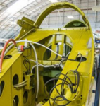
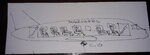
The P-39 has a lot of structure between the keel beams as shown in the photo Wuzak posted.Please expand the above drawing. This drawing explains exactly what I have been saying. The engine bay is 90.25" long. It extends from the aft edge of the cabin assembly to the bulkhead (with the hole in it) just in front of the oil tank. The entire engine and aux stage supercharger including carburetor are contained in that engine bay. It does not extend past the oil tank bulkhead.
The engine bay is exactly the same length on the P-39 as it is on this P-63. The aux. stage would fit in the P-39 engine bay after the coolant tank had been moved up to the top front edge of the engine as it is in this diagram. The XP39-E did not have a lengthened engine bay (as was often stated in reference books), it had a lengthened tail cone aft of the engine bay.
The P-63 has a lot of fresh air and one single cross member in the same area
Attachments
Last edited:
MiTasol
Captain
Hello P-39 Expert,
You are actually incorrect. While the engine on the P-39C/D/D-1/F was pretty comparable to that of the P-40E, the propeller was quite different.
Those P-39 used a 10 feet 4 1/2 inch propeller with a 1.8:1 reduction
The P-40E used a 11 feet 0 inch propeller with a 2:1 reduction
The power coefficient of the P-40E engine / propeller would suggest that it would be better suited (than the P-39) to higher altitudes..... Not that its supercharger was any better suited.
Another thing I have always wondered about is how effective the carb intake was on the P-39 for optimum ram effect. It looks like it would be sitting in a low pressure area. On the P-40, it is sitting at the nose in a high pressure area.
- Ivan.
Gidday Ivan, naturally you are correct and the reasons are so blindingly obvious to anyone who thinks.
For beginners it is totally impossible to fit a cannon thru a P-40 propeller hub because the pitch change motor is front and centre on the prop.
The P-40 blades are alloy. Some P-39 blades were alloy but many were hollow steel, another difference.
A further, very minor, factor is that the hub diameter on the P-39 props, both CE and AP, is far larger than the P-40 hub, as shown in the above diagrams, in order to accommodate the cannon down the shaft. This means the blades are a smaller percentage of the propeller diameter and the transition from circular profile to aerofoil is further from the prop centreline.
Being a smaller diameter that further reduces the percentage of the blade available to create thrust.
Can we call this another myth busted?
Last edited:
MiTasol
Captain
Please expand the above drawing. This drawing explains exactly what I have been saying. The engine bay is 90.25" long. It extends from the aft edge of the cabin assembly to the bulkhead (with the hole in it) just in front of the oil tank. The entire engine and aux stage supercharger including carburetor are contained in that engine bay. It does not extend past the oil tank bulkhead.
The engine bay is exactly the same length on the P-39 as it is on this P-63. The aux. stage would fit in the P-39 engine bay after the coolant tank had been moved up to the top front edge of the engine as it is in this diagram. The XP39-E did not have a lengthened engine bay (as was often stated in reference books), it had a lengthened tail cone aft of the engine bay.
The P-39 has a lot of structure to support the coolant tank and provide rigidity between the keel beams as shown in the photo Wuzak posted. In particular that bulkhead with the flanged lightening hole (visible behind the coolant tank support) between the two keel units adds a massive amount of rigidity to the structure as does that curved plate connecting both keel units.
The P-63 has a lot of fresh air and one single cross member in the same area in the forward fuselage and significantly less structure in the rear fuselage than the P-39 where the two fuselage halves join.
Front fuselage
Looking at this diagram below we again see that there is no bulkhead between the front and rear fuselage as you can see clear through into the forward fuselage. You will note that the oil return line (yellow) is totally hidden behind the metal part of the rear fuselage bulkhead (the edge being just to the right of the orange line. Have you ever wondered why they hid that pipe there when it would be so much more accessible for maintenance if it was inside the area that you say holds nothing but glider fuel. Now ask yourself why do they need to keep that area totally free of everything except glider fuel? Now tell my what your answer is.
Mine is the ASB partially occupies that area.
Please expand the above drawing. This drawing explains exactly what I have been saying. The engine bay is 90.25" long. It extends from the aft edge of the cabin assembly to the bulkhead (with the hole in it) just in front of the oil tank. The entire engine and aux stage supercharger including carburetor are contained in that engine bay. It does not extend past the oil tank bulkhead.
The engine bay is exactly the same length on the P-39 as it is on this P-63. The aux. stage would fit in the P-39 engine bay after the coolant tank had been moved up to the top front edge of the engine as it is in this diagram. The XP39-E did not have a lengthened engine bay (as was often stated in reference books), it had a lengthened tail cone aft of the engine bay.
Maybe it is time to go back to the basics that any airframe driver (pilot) and spanner wrencher (aircraft maintenance technician) learns about day one. Everything contained within the single area bounded by the cowlings and aircraft structure/skin is the engine bay or engine compartment. On the P-63 that includes everything from the firewall behind the pilot on the P-39/63 to the next full bulkhead. On the P-39 that is the bulkhead that the oil tank protrudes through. On the P-63 that is the bulkhead behind the oil tank. So you are right - it only extends as far as the oil tank bulkhead at station 253.
You will be pleased to know both aircraft are very questionable on these limits because there is no effective firewall at the back of the engine bay so one could also be technically accurate claiming the whole of the rear fuselage as engine bay. To say however that the engine bay ends at the fuselage joint line is a complete fallacy. The engine bay extends to the back of the oil tank.
To suggest that the designers went to all the trouble to move the tank as far back as they did, instead of just mounting it vertically behind the joint line bulkhead, for any reason except the engine installation needs that room for the back of the ASB and the associated plumbing, wiring and controls is equally fallacious.
MiTasol
Captain
The point is HOW MUCH do you move it and where and this becomes more critical if you're attempting to do this in the field. And again, are these W&B "variations" for specific aircraft or for an entire production run of a specific model or configuration?
There is actually some guidance on that in the P-39N-0 and N-1 manual. One of the primary differences, maybe the only primary difference, is which prop is fitted.
The manual includes a section on changing from the CE prop to the Aeroprop and that includes changing the gearbox armour plate. I do not know how much of that is because the Aeroprop has fittings that must pass through the armour and how much is for weight and balance but given the difference in prop weights I suspect both.
Last edited:
FLYBOYJ
"THE GREAT GAZOO"
There is actually some guidance on that in the P-39N-0 and N-1 manual. One of the primary differences, maybe the only primary difference, is which prop is fitted.
The manual includes a section on changing from the CE prop to the Aeroprop and that includes changing the gearbox armour plate. I do not know how much of that is because the Aeroprop has fittings that must pass through the armour and how much is for weight and balance but given the difference in prop weights I suspect both.
Manual? Flight or maintenance?
P-39 Expert
Non-Expert
NThey should be on blue prints, equipment lists or weight and balance charts (like the one shown for the P-39Q). This information varied in it's presentation between manufacturers.
I meant how do you get these pilot manuals?
FLYBOYJ
"THE GREAT GAZOO"
Found them on line, I think one of them was on here in the manuals areaN
I meant how do you get these pilot manuals?
JOCULAR MODE: ON
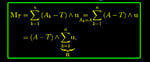
Once that with Varignon's theorem, that states that the torque of a resultant of two concurrent forces about any point is equal to the algebraic sum of the torques of its components about the same point ( in other words, "If many concurrent forces are acting on a body, then the algebraic sum of torques of all the forces about a point in the plane of the forces is equal to the torque of their resultant about the same point), in brief
 we have investigated the Moments of First Order, and so we have found the C.G of the "said" airplane.
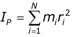
Let's now investigate the Moments of Second Order namely the Moment of Inertia, otherwise known as the mass moment of inertia, angular mass or rotational inertia.
That is a quantity that determines the torque needed for a desired angular acceleration about a rotational axis: it depends on the body's masses and the square of the distance of each mass from the axis chosen, with larger moments requiring more torque to change the body's rate of rotation.
In brief:

All this stated, a very rich man, but a very queer character

orders his Chief Pilot

to take an airplane out of his fleet to bring his guest to his private Caribbean Island.

Chief Pilot Pussy Galore choses an B-737/800 and 198 passengers ( mostly blondes) and their luggage are brought to the Island.

While Mr Goldfinger and his guests have jolly good time, he orders his Chief Pilot to smuggle in a nearby Country some of his gold, and also orders that all the gold ingost are to be hidden in the fore and aft toilets (he tipped the Customs, so they won't inspect there) and to fully load with gold the airplane. The volume of gold of the equivalent weight of the passengers is not that big, the gold can be stored in the toilets very easily.

Captain Galore is a very good Pilot (but she's not an aeronautical engineer…) so she divides the gold ingots between fore and aft toilets so that the C.G. (by Varignon's Theorem!) is exactly as it should be.
Now:
The weight of the airplane is within limits allowed.
C.G. is at the proper place.
Question:
Pussy Galore, on the return trip with the airplane laden of gold ingots will notice some "slight" differences in the "behaviour" of her B-737/800 or she will notice anything different?"
MODE JOCULAR: OFF
P.S. not taking into consideration structural problems, of course: fuselage will likely split in two but even before the floor of the toilets won't resist…
Once that with Varignon's theorem, that states that the torque of a resultant of two concurrent forces about any point is equal to the algebraic sum of the torques of its components about the same point ( in other words, "If many concurrent forces are acting on a body, then the algebraic sum of torques of all the forces about a point in the plane of the forces is equal to the torque of their resultant about the same point), in brief
Let's now investigate the Moments of Second Order namely the Moment of Inertia, otherwise known as the mass moment of inertia, angular mass or rotational inertia.
That is a quantity that determines the torque needed for a desired angular acceleration about a rotational axis: it depends on the body's masses and the square of the distance of each mass from the axis chosen, with larger moments requiring more torque to change the body's rate of rotation.
In brief:
All this stated, a very rich man, but a very queer character
orders his Chief Pilot
to take an airplane out of his fleet to bring his guest to his private Caribbean Island.
Chief Pilot Pussy Galore choses an B-737/800 and 198 passengers ( mostly blondes) and their luggage are brought to the Island.
While Mr Goldfinger and his guests have jolly good time, he orders his Chief Pilot to smuggle in a nearby Country some of his gold, and also orders that all the gold ingost are to be hidden in the fore and aft toilets (he tipped the Customs, so they won't inspect there) and to fully load with gold the airplane. The volume of gold of the equivalent weight of the passengers is not that big, the gold can be stored in the toilets very easily.
Captain Galore is a very good Pilot (but she's not an aeronautical engineer…) so she divides the gold ingots between fore and aft toilets so that the C.G. (by Varignon's Theorem!) is exactly as it should be.
Now:
The weight of the airplane is within limits allowed.
C.G. is at the proper place.
Question:
Pussy Galore, on the return trip with the airplane laden of gold ingots will notice some "slight" differences in the "behaviour" of her B-737/800 or she will notice anything different?"
MODE JOCULAR: OFF
P.S. not taking into consideration structural problems, of course: fuselage will likely split in two but even before the floor of the toilets won't resist…
Attachments
-
 00vbxzr1033.jpg13.4 KB · Views: 50
 -
 MomentInertia-56fd5a985f9b586195c6d7a0.jpg25.3 KB · Views: 57
 -
 goldfinger-1536x946.jpg153.1 KB · Views: 55
 -
 honor-blackman-and-tricia-muller-james-bond-007-goldfinger-signed-8x10-photo-pussy-galore-1631...jpg77.3 KB · Views: 60
 -
 1200px-Tortola-airport.jpg119.3 KB · Views: 57
 -
 Goldfinger A.jpg475.8 KB · Views: 45
Last edited:
P-39 Expert
Non-Expert
Where do you search onlne? Just asking, so I don't have to waste anymore of your time.Found them on line, I think one of them was on here in the manuals area
P-39 Expert
Non-Expert
You are correct on the propeller.Hello P-39 Expert,
You are actually incorrect. While the engine on the P-39C/D/D-1/F was pretty comparable to that of the P-40E, the propeller was quite different.
Those P-39 used a 10 feet 4 1/2 inch propeller with a 1.8:1 reduction
The P-40E used a 11 feet 0 inch propeller with a 2:1 reduction
The power coefficient of the P-40E engine / propeller would suggest that it would be better suited (than the P-39) to higher altitudes..... Not that its supercharger was any better suited.
Another thing I have always wondered about is how effective the carb intake was on the P-39 for optimum ram effect. It looks like it would be sitting in a low pressure area. On the P-40, it is sitting at the nose in a high pressure area.
- Ivan.
- Status
- Not open for further replies.
Users who are viewing this thread
Total: 1 (members: 0, guests: 1)