Peter Gunn
Master Sergeant
Quite possibly, thanks, I'll look it up and try to snag a copy.Hello Peter Gunn,
Could this be the book you are remembering?
It might not be the same edition or cover.
- Ivan.
View attachment 596772
Follow along with the video below to see how to install our site as a web app on your home screen.
Note: This feature may not be available in some browsers.
Ad: This forum contains affiliate links to products on Amazon and eBay. More information in Terms and rules
Quite possibly, thanks, I'll look it up and try to snag a copy.Hello Peter Gunn,
Could this be the book you are remembering?
It might not be the same edition or cover.
- Ivan.
View attachment 596772
With that last sentence in mind, I believe one should be careful about comparing ANY allied aircraft with the Aleutian A6M2.
Ach... double post, see post #104, apologies.It is quite interesting that even though this A6M2 was pretty beat up and bent before repairs, it still had no aborts or malfunctions during the testing. The same could not be said about some of the US aircraft in the test report (IIS 85).
They were a bit lucky that this was a fairly new aircraft and had not seen much service before the crash.
Here is a list of the repairs that were done just so folks can get a feel for how "intact" the A6M2 actually was:
A 15 August 1942 memo from the Commanding Officer of the U.S. Naval Air Station, San Diego, to the Chief of the Bureau of Aeronautics, listed repairs that Zero 4593 needed to make it airworthy. The following is a text of that memo, start:
1. Subject airplane can be put into flying condition in six weeks, provided no unexpected trouble is encountered. It will be necessary to manufacture numerous replacement parts, particularly bolts, machine screws, etc., as they appear to be metric. Work has commenced and will be expedited by day and night shifts, seven days a week.
2. The engine appears to be in good general condition. The bottom front cylinder was dented, apparently by the bullet, which severed the forward sump oil line. The Station will straighten and re-hone this cylinder, and it is believed that it will be in satisfactory condition. The carburetor and possibly other engine accessories are in bad shape internally from corrosion, and will need considerable reconditioning. No undue difficulty in accomplishing this is anticipated.
Structural Repairs Necessary to Fuselage and Wings:
1. Rebuild fin.
2. Repair both elevators.
3. Repair rudder.
4. Rear section of fuselage out of line and bulkheads buckled necessitating considerable repair.
5. Repair fuselage belt frame at stations 9 and 11.
6. Replace top fuselage skin and stringers
7. Rebuild sliding cockpit enclosure
8. Repair seat
9. Straighten fuselage adjacent to cockpit both sides at stations 2-5.
10. Repair fuselage skin at station 4.
11. Repair fuselage at top forward of pilot at station 1.
12. Rebuilt entire engine cowling
13. Repair cowl flaps.
14. Rebuild both sides of landing gear (both main attaching fittings sheared off).
15. Rebuild left landing flap.
16. Replace all ribs on right landing flap.
17. Cut and splice main left wing beam at landing gear attachment.
18. Rebuild one wing tip.
19. Repair left bottom wing skin at station 2.
20. Repair bullet holes in left wing at station 0.
21. Repair leading edge skin on right wing at stations 1.4 and 2.
22. Remake gun cover in right wing between stations 2 and 2.25
23. Patch right wing leading edge skin at station 3.
24. Patch skin and splice main wing bulkhead at station 3.7.
25. Manufacture two aileron fittings which have been sawed off.
26. Replace pilot tube located on left wing.
27. Manufacture various nuts, bolts, etc. which are missing and patch various small holes in skin.
28. Check all wiring. It may be necessary to replace fifty percent of wiring in ship.
29. Test oil and gas tanks. Overhaul is probably necessary.
30. Re-rig all surfaces and other controls.
Necessary Engine Repairs:
1. Straighten and repair nine push rods.
2. Repair one cylinder.
3. Rewire and overhaul harness.
4. Replace two missing spark plugs with LS321 plugs.
5. Completely overhaul carburetor (badly corroded - all springs and some other parts to be replaced)
6. Recondition magnetos (badly corroded).
Instruments:
1. Overhaul all instruments, hydraulic units.
2. If necessary, replace instruments and other small units with Navy standard articles.
End.
it lacked a supercharger that limited its effectiveness above 17,000 feet.
I think George made a typo, omitting the words "two stage" ahead of supercharger.P-39 was always powered by a supercharged engine.
I think George made a typo, omitting the words "two stage" ahead of supercharger.
Did weigh 8900lbs though, right? Wonder how it would have performed in a regular P-39 at 7900lbs?Two stage Allison -47 was running in the P-39E in April 1942. Problem was the extensively revised E model weighed 8900lbs. Had six .50cal MGs AND a 37mm cannon. And didn't have a 4 blade propeller.
Let's see.
Two stage Allison -47 was running in the P-39E in April 1942.
Yep, true, sort of, an Allison -47 was running in the P-39E in APril of 1942, but in what configuration?
There were 3+ Allison -47 built. over 4000 on order at one point but either canceled or changed to other versions.
The -47 was eventually turned into the -93.
The -47 was initially built with an auxiliary supercharger using the same diameter impeller as the engine supercharger and fixed speed (single) drive. This was while still on test bench.
The drive system was modified a number of times to finally get to the configuration used in the P-63, hydraulic coupling with variable speed.
The -47 was rated at 1150hp at 21,000ft at some point (not April of 1942, they had not finalized the drive system yet, they decided to use the automatic hydraulic coupling in July of 1942) engine weighed 1525lbs in Feb of 1942.
The developed -93 engine was designed in the fall of 1942, not fully prepared for model testing until May of 1943.
Yep, lets use a near vaporware engine.
Had six .50cal MGs AND a 37mm cannon
No, it didn't. That armament was proposed by Larry Bell in a letter to General Echols in the spring of 1942 when they were asking for funding for a 3rd XP-39E to be built after the first one crashed. He also proposed a low altitude version of the engine with 1500hp at 3000ft. to power this version which Larry Bell envisioned as an attack plane for use against invasion forces attacking the United States. WEP ratings had not been approved for US engines at this point.
Please find any photo or drawing of an XP-39E with any wing guns, even the .30 cal ones.
need for 4 bladed propeller to handle 1325hp for take-off and 1150hp at 21,000ft seems a little iffy. Need for a 4 blade propeller won't show up until some time in 1943.
Was a little faster than 376mph at 15000'. Would outclimb anything in 1943 except a Spitfire IX.From this site...The P-39 Airacobra - Warfare History Network
".....At the same time, the plane was considered underpowered with its 1,200 horsepower Allison V-1710 engine, although it could do 376 miles per hour at 15,000 feet. Also, it lacked a supercharger that limited its effectiveness above 17,000 feet. Worse, the P-39 had a reputation for tumbling out of control when operated by inexperienced pilots....
Was a little faster than 376mph at 15000'. Would outclimb anything in 1943 except a Spitfire IX.
Yeah, real simple.Just an impeller in a diffuser with a hydraulic coupling turned by a shaft from the starter. Pretty simple, just took forever.
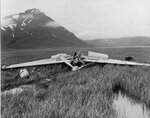
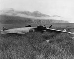
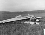
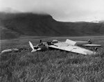
Very informative. After having read about the capture of an intact Zero in probably every book about the Battle of Midway, it doesn't look quite so intact.It is quite interesting that even though this A6M2 was pretty beat up and bent before repairs, it still had no aborts or malfunctions during the testing. The same could not be said about some of the US aircraft in the test report (IIS 85).
They were a bit lucky that this was a fairly new aircraft and had not seen much service before the crash.
Here is a list of the repairs that were done just so folks can get a feel for how "intact" the A6M2 actually was:
A 15 August 1942 memo from the Commanding Officer of the U.S. Naval Air Station, San Diego, to the Chief of the Bureau of Aeronautics, listed repairs that Zero 4593 needed to make it airworthy. The following is a text of that memo, start:
1. Subject airplane can be put into flying condition in six weeks, provided no unexpected trouble is encountered. It will be necessary to manufacture numerous replacement parts, particularly bolts, machine screws, etc., as they appear to be metric. Work has commenced and will be expedited by day and night shifts, seven days a week.
2. The engine appears to be in good general condition. The bottom front cylinder was dented, apparently by the bullet, which severed the forward sump oil line. The Station will straighten and re-hone this cylinder, and it is believed that it will be in satisfactory condition. The carburetor and possibly other engine accessories are in bad shape internally from corrosion, and will need considerable reconditioning. No undue difficulty in accomplishing this is anticipated.
Structural Repairs Necessary to Fuselage and Wings:
1. Rebuild fin.
2. Repair both elevators.
3. Repair rudder.
4. Rear section of fuselage out of line and bulkheads buckled necessitating considerable repair.
5. Repair fuselage belt frame at stations 9 and 11.
6. Replace top fuselage skin and stringers
7. Rebuild sliding cockpit enclosure
8. Repair seat
9. Straighten fuselage adjacent to cockpit both sides at stations 2-5.
10. Repair fuselage skin at station 4.
11. Repair fuselage at top forward of pilot at station 1.
12. Rebuilt entire engine cowling
13. Repair cowl flaps.
14. Rebuild both sides of landing gear (both main attaching fittings sheared off).
15. Rebuild left landing flap.
16. Replace all ribs on right landing flap.
17. Cut and splice main left wing beam at landing gear attachment.
18. Rebuild one wing tip.
19. Repair left bottom wing skin at station 2.
20. Repair bullet holes in left wing at station 0.
21. Repair leading edge skin on right wing at stations 1.4 and 2.
22. Remake gun cover in right wing between stations 2 and 2.25
23. Patch right wing leading edge skin at station 3.
24. Patch skin and splice main wing bulkhead at station 3.7.
25. Manufacture two aileron fittings which have been sawed off.
26. Replace pilot tube located on left wing.
27. Manufacture various nuts, bolts, etc. which are missing and patch various small holes in skin.
28. Check all wiring. It may be necessary to replace fifty percent of wiring in ship.
29. Test oil and gas tanks. Overhaul is probably necessary.
30. Re-rig all surfaces and other controls.
Necessary Engine Repairs:
1. Straighten and repair nine push rods.
2. Repair one cylinder.
3. Rewire and overhaul harness.
4. Replace two missing spark plugs with LS321 plugs.
5. Completely overhaul carburetor (badly corroded - all springs and some other parts to be replaced)
6. Recondition magnetos (badly corroded).
Instruments:
1. Overhaul all instruments, hydraulic units.
2. If necessary, replace instruments and other small units with Navy standard articles.
End.
Yes, but...it's a tribute to the genius of Horikoshi Jiro that the basic airplane was so simple, straightforward, and non-critical that foreigners accustomed to different hardware, structural materials and design practices, and no usable documentation could repair it, rig it, and flight test it with no manufacturer support. And in a manner that delivered bulletproof reliability.Very informative. After having read about the capture of an intact Zero in probably every book about the Battle of Midway, it doesn't look quite so intact.
Yes, but...it's a tribute to the genius of Horikoshi Jiro that the basic airplane was so simple, straightforward, and non-critical that foreigners accustomed to different hardware, structural materials and design practices, and no usable documentation could repair it, rig it, and flight test it with no manufacturer support. And in a manner that delivered bulletproof reliability.
When a twin row radial suffers a prop strike/sudden stop, an awful lot of rotating mass comes to an abrupt halt, deforming internal parts, which under normal circumstances would be replaced. If you have no spares, no drawings, and no table of limits, reconstituting said parts entails a lot of "by guess and by golly" and infinite opportunities for getting it wrong. Ask our Allison Man, Greg P, how critical these things are in rebuilding an engine, especially one with unfamiliar tolerances, an unfamiliar measurement system, unfamiliar design practices, and no documentation.
Quite likely he was at flight idle or slightly above, as he was trying to make a smooth landing in a grassy field of unknown roughness. I have a book about this Zero with pictures in which the third propeller blade is visible, and it clearly took a hit, stopping the engine from maybe 900-1000 RPM in 1/3 revolution to a dead stop. Yes, the con rods were bent, according to the report of the repairs, not unusual for a reduction geared twin row radial. Two master rods, twelve connecting rods, fourteen pistons, a supercharger disk, a planetary gearset, and a propeller, all slammed to a stop at once in less than half a revolution, something's going to give.I was wondering about the prop strike until I looked at the pictures. It appears either the motor was rotating very slowly or had stoped. In the previous shots you can see he basically came down in a marsh and the props appear to have no noticeable damage.
The climb numbers for Faber's 190A-3 as tested by the British have always been an outlier. No other 190A approached that level of climb. Interesting that the British could only get 375mph at 18000' out of it.Hello P-39 Expert,
I take it you must not have seen the testing of Faber's FW 190A-3 or USN testing of a FW 190A-5/U4.
I believe the A-3 was almost a year earlier and the A-5/U4 had a higher rate of climb AND better speed without running Emergency power.
The early Me 109G was also a bit faster and had comparable climb rates but I am not sure when their engines were cleared to run full manifold pressure.
- Ivan.
The climb numbers for Faber's 190A-3 as tested by the British have always been an outlier. No other 190A approached that level of climb. Interesting that the British could only get 375mph at 18000' out of it.
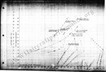
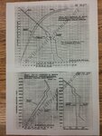
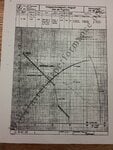
Regarding the Navy test of the 190A-5 it climbed about the same as the Hellcat and Corsair. Attached climb graphs of the 190A-6 and the Hellcat show that the P-39N outclimbed both substantially at all altitudes.