XP-39 Wind Tunnel Tuft Tests

Ad: This forum contains affiliate links to products on Amazon and eBay. More information in Terms and rules

The P-40 did not need a boundary layer splitter - there was little or no boundary layer at that point, as the radiator intake was right behind the spinner.
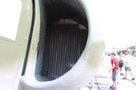
That's why the belly-radiator didn't work on all aircraft?
The P-38 did, albeit a duct rather than a splitter.
I never saw the radiator up close like this before, but I get it.
And the P-39 had flaps to control the mass flow through the radiator
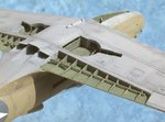
I'm curious if it would have been possible to extend the radiator a bit forward like the XP-40Q?[/QUOTE]
 

Attachments

  • p40-23.jpg
    p40-23.jpg
    76.3 KB · Views: 265
  • p-38-107w-3.jpg
    p-38-107w-3.jpg
    40.1 KB · Views: 243
  • p39kws_2.jpg
    p39kws_2.jpg
    48.2 KB · Views: 282
Last edited:
I think one or two of the XP-40Q prototypes had leading edge radiators.

The P-39 had its radiator buried in the fuselage, fed by leading edge intakes (P-63 too, I think).
 
Like on the P-63?
The P-63 or F4U arrangement could work. Something like the De Havilland Mosquito or Hornet could work as well.

Or would you rather some underwing radiators like on the Aeobonita?
Those didn't seem to work out too good, though I do remember seeing three movable doors on the underside of your model, and a small radiator could cover that.
 
I am not sure what you are trying to accomplish?

The cooling problems were fixed on the XB-39B and YP-39As. Air went in the wing root intakes, was routed to the center section between the wheel wells and out through the doors/flaps underneath. This worked just fine for all the production P-39s until 1944. There were two radiators and one oil cooler.
P-63 needed bigger ducts, more cooling for several reasons. One is that while the P-39 set up not only worked for the initial 1090hp engine it was able to work for the later 1200-1325hp engines, of course they only made big power down low where the air is dense so mass airflow through the system wasn't too big a problem. Also the single stage engines only used up about 100hp in friction and about 200hp to drive the supercharger so total cooling load was about 1500-1600hp in the cylinders.
With the P-63 flight at higher altitudes was planned with less dense air so you need more cubic feet even for the same power. The mechanical drive 2nd stage (or Aux stage) required up to 300 hp to drive it (going by memory could be wrong) if operating at it's highest gear ratio (variable drive) so the cooling system has to be big enough for the 1800-1900hp cooling load to get 1325hp to the prop at 25,000ft.
An inter-cooler was planned for the P-63 (at least for some engines) but the sub contractor couldn't deliver (or more than one sub contractor?). At least that is what one book claims. Where it was supposed to go I don't know.
Please note that for inter-coolers to be effective they need 2-3 (or more) times the amount of cooling air as intake for the engine. In other words, even a a well designed system is going to need a scoop 2-3 times the size of the scoop behind the canopy of the of the P-39 or P-63.
Turbos had their own cooling problems which is why every production installation except the P-47 had them hanging part way out of the airplane. You have to keep the turbine blades from getting so hot that they fail. And a lot of the service installations were not far from that point. There was a reason that they were placed a number of feet from the engine (exhaust could cool a little) and still had pieces of steel plate to catch/deflect thrown turbine blades from hitting aircrew.
 
This may or may not be a good place to bring this up, but the current Mercedes Formaul 1 engine has a rather revolutionary turbocharger. The exhaust turbine is on one end of the engine and the shaft runs all the way through the engine block to the other side, so the compressor wheel is nowhere NEAR as hot as for a conventional turbocharger, being far removed from exhaust heat of any kind.

Nobody thought of that back in WWII, but I wonder if it could have significantly affected turbo developement all those years ago? Interesting, but sort of an over-the-top "what-if" that really requires no further development. I mentiom it only for completeness as, had someone thought of it, it is possible turbos would have been much more developed by the time the big pistons were going extinct, and higher altitude pistons might have been the norm.

End of side track ... back to reality, please continue.
 
I am not sure the problem was heat transfer from the turbine section to the compressor section.

P-47 turbo:
marchmussupercharger107w-1.jpg

There seems to be a heat shield / cooling duct between the Turbine casing and the compressor casing. Granted some heat could still get through and some be conducted along the shaft.

Only gone through a couple of websites in the Mercedes F1 so I may be reading something wrong but it appears the Turbine drives a generator that feeds a battery pack. The supercharger is electric powered? Battery pack also feeds power to electric motors in rear wheels upon demand (under braking wheel motors act as generators to feed electricity back into the battery)

Haven't found the boost level yet but would bet dollars to donuts that the F1 engine is running higher pressure than the P-47 turbo alone.

The main advantage of the Mercedes turbo is for packaging in the car.

The current F1 V6 Hybrids consist of a 1.6l V6, turbocharger with attached motor/generator unit (MGUH, H for heat), a battery pack and a motor/generator unit connected to the crankshaft of the engine (MGUK, K for kinetic).

The MGUH can be used to drive the turbo, when rpm is low or when in qualifying mode allowing the wastegates to open, reducing back pressure and increasing power.

And it can also be used to generate power, recovered from the exhaust energy. This can be sent to the battery pack, or directly to the MGUK connected to the engine. The regulations specify that only 4MJ of energy can be sent from the battery pack to the MGUK, but i=unlimited energy can be transferred between the battery and the MGUH and between the MGUK and MGUH. The effect is that for most of the time the engine works as a turbo-compound, feeding recovered power back to the output shaft.

The compressors run a pressure ratio in the region of 3 - 4:1. Exactly how much is secret.

Mercedes' layout allows the MGUH to be placed between the turbine and compressor and in the engine's vee.
Ferrari's original turbo also placed the MGUH between the turbine and compressor, but the whole assembly was behind the engine. This has since been changed to a system that Renault has run, with turbo and compressor together, with the MGUH in front of the compressor in the vee.
Honda have the MGUH between turbine and compressor, but in their case the compressor was in the engine's vee. For 2017 they are changing to the Mercedes layout. Renault and Ferrari may do also - restrictions which prevented them from changing their layouts before have been lifted.

The net result of this is an engine which produces nearly 800hp from the ICE alone, around 950hp with all the energy recovery deployed. All with a restricted fuel flow rate of 100kg/h. With thermal efficiency is approaching 50%.
 
Hi Shortround,

Nice pic. GE C-23, I think. Did you notice it is labeled incorrectly in today's terminology? The unit WAS called both a supercharger a turbo-supercharger in WWII, but is a turbocharger today. I suppose period terminology is only fitting, though.

About the pic Shortround ... all the parts were metal, right? If metal was any good as an insulator, nobody would use metal pots and pans to cook with.

In the case of the Mercedes F1 engines of today, the compressor is far removed from exhaust heat and the cooling is much superior to regular turbochargers. They rather obviously haven't made public how much less intercooling is required, but that engine is making an easy 50 - 80 Hp more than others. Most of the non-Mercedes F1 engines are making some 820 Hp while the Mercedes, with the same displacement, is making 870+ HP, and quite reliably. That's 6 to 7.9% more power with no other obvious technology changes. In a 2,000 HP engine, that might give 120 - 158 more HP for free. While not exactly earth-shaking, more it is better.

Again, though, I am NOT intending to open a Formula 1 discussion, just wondering how much it would help a 1940's-technology turbocharger to have separated the turbine wheel and the compresor wheel by a distance of some 2 meters. I don't really expect anyone can answer that and do NOT want to take us off topic. If we DO discuss it, maybe in a separte thread?

Seems like a potentially-intertesting subject, but also one for which we would all have zero data and no possibility of data. That just makes for a long technical thread that is of limited value without a conclusion based in fact.

After I posted I looked above, and I see we're wandering off-topic badly and will desist starting here, unless in a separate thread. Good post, Wayne. Thing is, everybody has the same rules and everybody is running the MGUH and all the rest, not just Mercedes. Their ONLY advantage is the better turbocharger. Everyone else has all the rest of very equal technology. That was my point. The Mercedes advantage almost has to be mostly turbocharger only, or else you are implying everyone else isn't as good as Mercedes with technology. And I think all the teams have very good technical expertise, not just Mercedes.

So, maybe a separate thread? In any case, good post, as usual.

Back to XP-39!

So far, Shortround's assessment taht the P-39 was troo small to accept everything required for a turbochargerd piston fighter early in the U.S. P-39 development seems to be the best summary of the type. Perhaps we might consider all development, including maybe a 2-stage Merlin, in a P-63?

At least that is more or less on topic. The P-63 had potential and was a very good fighter, but it also wasn't a long-range fighter. I am not sure if the airframe could handle both a Merlin setup AND more fuel for increased range, and still remain a good fighter, but we CAN make a supposition that it didn't have to fight wih a large full-fuel load.

The P-51 was abysmal when the fuselage tank behind the pilot was full and it also had drop tanks, but it was employed that way nonetheless on thousands of occasions because lighter P-51s were covering for the heavier ones until the heavier ones got lighter and could fight. That is, the burdened fighters were at the rear, burning fuel and the lighter ones fought up front and then left for home when the rear echelon guys got lighter and could handle things.

Perhas a similar thing could be worked out for a 2-stage Merlin-powered P-63. Again, though, it would have to gain something over the P-51 before it would make sense to acquire it for USAAF use. Since we obviously have zero data on that, it is another argument possibly without a good answer, other than our opinions.

I lean toward the 2-stage Merlin making the P-63 a better plane than it was, and I already think it was pretty good relative to a P-51. Making it even better might make it a good candidate for acquisition, but I'd have to see data ... and there isn't any. So, my opinion is that it would probably gain at least parity with the P-51 with just the Merlin swap, and I dont know if extra fuel could be accommodated or not. I'm SURE you ccould get the fuel in there, but the question in my mind is whether or not you could get it in and still remain with a good CG limit. The P-39 had issues with that. Changing it might introduce the same in the P-63, and the only way to know would be to have someone familiar with the P-63 design analysis calculate estimated performance, including extra fual and CG envelope.

Personally, I lack a wind tunnel, the requisite equipment, an accurate scale model, the funds, and the desire to do it. That pretty much rules me out, even from the interest side, since there is no possible use for the data 70 years after the fact.

I think we are stuck with the P-39 not being able to be developed into a useful fighter at it's real-world size, and maybe the P-63 could have been. In the event, we all know what happened. They built a lot of P-63s, but we didn't use them.
 
Last edited:
The insulation doesn't come from the metal it comes from the airspaces on either side of the heat shield.

Much like the heat-shields on catalytic converters keep your floor mats from melting :)
94300sectional.jpg

doesn't mean they don't get warm.

Old text book says an auxiliary supercharger that is raising the ambient air pressure to sea level pressure and is 65% efficient will raise the air temperature by 210-220 degrees F at 25,000ft. Granted the ambient air at 25,000ft is pretty cold but the compressor section is going to be pretty warm all on it's own.

Heat gets transferred 3 ways. Conduction (heat passed through common parts like the shaft of the turbo assembly). Convection ( hot air/gases leaves the hot surface/combustion and travels to the new surface/object. And radiant heat, Those infrared waves that travel in straight lines (and can go through glass). Metal heat shield blocks the radiant heat (at least until the heat shield gets really hot.) and with air flowing on both sides of the heat shield the convection heat path is removed. With air flowing over the heat shield the heat shields ability to operate as a radiator is diminished. Conducted heat has to get into the shaft, flow down the shaft and then heat up the compressor disk. However the heat has had to flow past two oil lubricated bearings which may take some of the heat away.

Cut away Turbo
pimamussupercharger107w-1.jpg


Heat shield and airflow provided by turbine blades?
 
In the case of the Mercedes F1 engines of today, the compressor is far removed from exhaust heat and the cooling is much superior to regular turbochargers. They rather obviously haven't made public how much less intercooling is required, but that engine is making an easy 50 - 80 Hp more than others. Most of the non-Mercedes F1 engines are making some 820 Hp while the Mercedes, with the same displacement, is making 870+ HP, and quite reliably. That's 6 to 7.9% more power with no other obvious technology changes. In a 2,000 HP engine, that might give 120 - 158 more HP for free. While not exactly earth-shaking, more it is better.

The distance between the compressor and the turbine on the Mercedes F1 engine is about a foot.

Ferrari are said to be line ball with Mercedes in terms of power, except in qualifying mode.

Renault and Honda are not far behind.

Over-cooling of the intake air destroys the efficiency of these engines, and hence reduces power. Both Mercedes and Ferrari use an air to air interooler and a water to air intercooler. Presumably this is to give finer control of cooling.
 
shortround said:
I am not sure what you are trying to accomplish?
Somewhere along the way, it was mentioned that the intakes had issues flowing around the tight kinks produced by the landing-gear door positions. So I figured...
The cooling problems were fixed on the XB-39B and YP-39As.
Of course, there was no secondary stage of supercharging and no cooler needed as a result.
There were two radiators and one oil cooler.
Okay, so the center was the oil-cooler, and the left and right were the radiators?
P-63 needed bigger ducts, more cooling for several reasons. One is that while the P-39 set up not only worked for the initial 1090hp engine it was able to work for the later 1200-1325hp engines, of course they only made big power down low where the air is dense so mass airflow through the system wasn't too big a problem. Also the single stage engines only used up about 100hp in friction and about 200hp to drive the supercharger so total cooling load was about 1500-1600hp in the cylinders.
I never realized friction would have been factored seperately, I figure anything needed to drive the supercharger would be weighted against the extra horsepower produced...
Please note that for inter-coolers to be effective they need 2-3 (or more) times the amount of cooling air as intake for the engine. In other words, even a a well designed system is going to need a scoop 2-3 times the size of the scoop behind the canopy of the of the P-39 or P-63.
What reduces the cooling-air requirements and space requirements?
Turbos had their own cooling problems which is why every production installation except the P-47 had them hanging part way out of the airplane.
How did they get around it?
You have to keep the turbine blades from getting so hot that they fail.
I understand that, admittedly it's mostly from a knowledge of jet-engines, but...
There was a reason that they were placed a number of feet from the engine (exhaust could cool a little) and still had pieces of steel plate to catch/deflect thrown turbine blades from hitting aircrew.
I thought that was simply so the exhaust would be reasonably smooth through the turbine, but I had no idea of the use of armor plates to catch the turbine so the pilot wouldn't get skewered.


BTW: I'm not capable of quoting and pasting at this time for some reason, so I'm doing it the old fashioned way...
 
Last edited:
Somewhere along the way, it was mentioned that the intakes had issues flowing around the tight kinks produced by the landing-gear door positions. So I figured...
Of course, there was no secondary stage of supercharging and no cooler needed as a result.

Well you can't have everything :)

You want the turbo and intercooler you accept the weight and drag and the poorer performance at 15,000 and below. Turbo only shows real advantage at 20,000ft and up with the 15-20,000ft area being a toss-up/crossover. There is no free lunch.

Okay, so the center was the oil-cooler, and the left and right were the radiators?
I was in error, Tomo is correct. One square or rectangular radiator in the center and a round oil cooler to either side in their own ducts.

I never realized friction would have been factored seperately, I figure anything needed to drive the supercharger would be weighted against the extra horsepower produced...

When figuring out the size of the radiators/oil coolers you need to find out what the power being produced in cylinders was, not the power going to the propshaft. Friction changed from about 100hp in the early C series engines (long nose) to around 200hp in the late engines that made 1600hp and up in WER mode. Different piston rings, different valve springs and a few other details. Power to drive pumps (oil, water and fuel) was usually included in friction) They actually hooked the engine up to an electric motor and subtracted-added parts while measuring how much power it took to turn the engine over at the desired RPM. Like running it without connecting rods/pistons or cylinder heads to figure friction in the main bearings.

What reduces the cooling-air requirements and space requirements?
Nothing unless you can repeal the laws of physics. You can sometimes do a better job of packaging but please remember that every bend in the ducts and every change in the cross section of the ducts can bring their own losses so you can't just jam everything in tighter. B-17s actually had slightly different full throttle heights on inner and outer engines due to differences in the duct work. Same engines, same turbo, same intercooler.

How did they get around it?

P-47 used a big enough air intake to be able to split off some air to cool the turbo.
 
Last edited:
tomo pauk said:
The P-39 have had two oil coolers/radiators, and one coolant radiator. P-63 was with two oil coolers/radiators and two coolant radiators.
Which was due to thee more powerful engine?

Well you can't have everything :)
What about surface evaporative cooling for the engine and a normal radiator for the intercooler :crazy:?
You want the turbo and intercooler you accept the weight and drag and the poorer performance at 15,000 and below.
How much drag would you say would present?
Turbo only shows real advantage at 20,000ft and up with the 15-20,000ft area being a toss-up/crossover.
15,000 to 20,000 feet being about the same seems acceptable, and much of the performance advantages the USAAF had demonstrated over the Luftwaffe were over 22,000 feet...
When figuring out the size of the radiators/oil coolers you need to find out what the power being produced in cylinders was, not the power going to the propshaft. Friction changed from about 100hp in the early C series engines (long nose) to around 200hp in the late engines that made 1600hp and up in WER mode.
How does the radiator size scale in proportion to these figures (i.e. hp to square or cubic inch).
B-17s actually had slightly different full throttle heights on inner and outer engines due to differences in the duct work. Same engines, same turbo, same intercooler.
I never knew that...
P-47 used a big enough air intake to be able to split off some air to cool the turbo.
I was thinking about the inter-cooler, and I was wondering: Did the US ever use liquid cooling for this purpose other than the Merlin 60's?
 
Last edited:
What about surface evaporative cooling for the engine and a normal radiator for the intercooler :crazy:?
Surface cooling only worked for racing planes. It generally required a lot of maintenance to deal with leaks let alone enemy fire.

How much drag would you say would present?
the two mock ups Bell tried with add on turbos were 30-40mph slower than standard P-39s at low altitude. Even cutting that to 20mph with a lot of attention to detail leaves the P-39 with little speed advantage at low altitude over the Zero.
How does the radiator size scale in proportion to these figures (i.e. hp to square or cubic inch).
It doesn't because not all radiators were the same depth front to back, and not all designers used the same pressure drop through the radiator.
I was thinking about the inter-cooler, and I was wondering: Did the US ever use liquid cooling for this purpose other than the Merlin 60's?
Not on service aircraft, not sure about prototypes. Liquid cooling helps with packaging, it is a lot easier to run a few fluid filled lines than large air ducts. It doesn't help so much with actual heat dissipation. Instead of cooling air flowing through inter-cooler with hot air in the alternate passages you replace it with water/antifreeze. Yes the intecooler may be able to be made smaller but now you need the intercooler radiator and you need XXX number of pounds per minute of cooling air to cool the inter-cooler fluid.
 
Surface cooling only worked for racing planes. It generally required a lot of maintenance to deal with leaks let alone enemy fire.

the two mock ups Bell tried with add on turbos were 30-40mph slower than standard P-39s at low altitude. Even cutting that to 20mph with a lot of attention to detail leaves the P-39 with little speed advantage at low altitude over the Zero.

It doesn't because not all radiators were the same depth front to back, and not all designers used the same pressure drop through the radiator.

Not on service aircraft, not sure about prototypes. Liquid cooling helps with packaging, it is a lot easier to run a few fluid filled lines than large air ducts. It doesn't help so much with actual heat dissipation. Instead of cooling air flowing through inter-cooler with hot air in the alternate passages you replace it with water/antifreeze. Yes the intecooler may be able to be made smaller but now you need the intercooler radiator and you need XXX number of pounds per minute of cooling air to cool the inter-cooler fluid.
 

Users who are viewing this thread

Back