kool kitty89
Senior Master Sergeant
View: https://www.youtube.com/watch?v=vKxe8jc9_rI
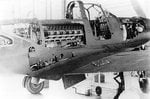
I'm surprised I've never stumbled on this video before, it's amazingly informative. The few photos of the XP-39 floating around and limited information (often misinformation) regarding its layout and turbocharger (and radiator) installation don't do it justice at all. (in fact, none seem to show the starboard side of the aircraft at all)
It might just be me, but the entire cooling system installation (oil cooler, intercooler, and to at least some extent coolant radiator) look shockingly sloppy and patched together ... almost taped-on. (except the coolant radiator which just seems awkwardly placed, or at least its exit duct mounted mid-wing towards the trailing edge ... below, and possible ahead of the intercooler scoop and turbo air intake) No boundary layer splitter/sleeves/cowls either, but that's not really surprising compared to the rest.
I had an inkling that the overall installation on the XP-39 was so bad as to be totally non-indicative of a practical turbocharger installation (even a reasonably acceptable draggy one with external intercooler -like the P-38J), but I didn't think it was this bad.
Additionally, note the comment about the wing stalling all at once (or almost simultaneously), though I'm not sure if this is relevant to the production P-39. (stall warning is supposed to be good, it's just the spin characteristics that are poor, at least when loaded tail-heavy or out of ammunition -the NACA-recommended 13 inch rear-fuselage extension probably didn't help, let alone the load of equipment crammed behind the engine)
Also interesting that the XP-39 has a nicer clear-view canopy, both taller and lacking the thick 'anti-roll bulkhead' behind the pilot. (an odd addition, I don't think any other WWII aircraft implemented roll-bars, and if they did they were omited in the bubble canopy redesign. (granted, this is a feature I noticed long ago with the more common pictures of the XP-39, though I only realized the full function of that bulkhead recently)
See:
http://img525.imageshack.us/img525/2236/bellairacobrai1939airen.jpg
(also note the small 60-round 20 mm ammunition drum, and the holes in the forward nose bulkhead for the omitted pair of 30 cal nose guns present on the YP-39 and P-39C, though there looks like enough space for another pair of .50 cal guns, but perhaps not ammunition boxes)
Edit:
on this issue (cut from earlier in my post)
This actually makes the quoted speed of the XP-39 with turbocharger rather more impressive with all that drag holding it back, admittedly with a lot less weight as well. (also makes me slightly more dubious over the 'excessive drag' created by attempted saddle-mounted turbo installations and other experimental fits tried ... unless those were all only on paper, so less attempted and more anticipated)
I see Shortround addressed this bit of misinformation as well a few years back:
Tomo, this has been gone over in other threads, but basically, The XP-39 did not meet the performance numbers promised.
There is no real evidence that it ever came close to the numbers given for in many books/web sites. And there is evidence that it couldn't have done what is claimed during the time period it is claimed it flew those numbers.
1. There was a potential problem with drive-shaft vibration that called for a redesigned heavier drive shaft to be fitted, This was not done until after the NACA wind tunnel tests and until fitted the engine was restricted to 2600rpm. No where near full power.
2. XP-39 was plagued with both oil and coolant overheating problems which called for redesign of both the oil cooler and radiator ducts.
3. General Arnold was making arrangements less than a month after it's flight to have the XP-39 put into the full size wind tunnel at Langley.
4. Contract weight was 5,550lbs, when weighed at Wright field during "expedited" acceptance trials it weighed 6,104lbs. about 10% over weight.
Many people claim that army generals and the NACA "ruined" the P-39. They never go into any details except to say they removed the turboPlease note the above was before the NACA got their hands on the P-39.
In their report they (the NACA) claim the XP-39, as they received it was good for 340mph at 20,000ft and just under 280mph at sea level.
There were severe problems with the airflow for the radiator, oil cooler and intercooler.
For the last, US practice of the time was that the intercooler should remove 1/2 of the heat added by the turbo-supercharger to the intake air before it entered the engine carburetor. In the XP-39 the NACA estimated the intercooler (based on airflows) was removing only 25% in high speed flight and about 12% during climb. This significantly affected power output. The inter cooler was small in size to fit the airframe and had a high pressure drop across it. this meant high drag. The XP-39 needed a much larger intercooler to perform properly and this larger intercooler would not fit in the airframe.
Bell did at least two mock-ups of turbo/intercooler units in 1941 to be 'added' to the P-39. the extra drag of these units caused 40-45mph speed loss at the lower altitudes.
340 mph at 20,000 ft I would buy with that 'streamlining' on the XP-39.
Though in that same thread:
XP-39: pros cons
Shortround got this bit wrong, given the oil cooler is clearly in a bulky external box on the XP-39 (an understandable mistake given the confusing information floating around, and that video being the only source showing the oil cooler at all)And on the XP-39 the oil cooler and radiator were in the wing root area ahead of the wheel, but to have good airflow you also need an exhaust duct behind the the radiators/coolers.
The XP-39 used the wing center-section for the turbocharger, with the radiator in the port wing center section (outlet in trailing edge). The XP-39A (and all later models) appear to have moved the radiator to the center section (port side) and the oil cooler(s) alongside it (starboard side) with the intakes for each in the corresponding wing leading edge.
On a side note, scanning the remainder of that thread's discussion: to increase fuel capacity, the best option seems to be deleting the wing armament and adding fuel cells to the outer wing compartments (that would otherwise hold the guns and magazines) and possibly in the wing leading edge. (the portion ahead of the gun bay is already clear to accommodate the blast tubes, but inboard of that may not be, and much further outboard gets too tight for useful fuel compartments very fast, so a pair of small leading-edge reserve tanks seems mostly likely) Beyond that you'd have to resort to tip-tanks, which would've been neat (and likely helped roll rate and possibly even stall/spin -due to wing-fence/winglet-like behavior) but the tip-tank arrangement seems to be too unusual and counter-intuitive for the time to be an obvious solution. (or sheer coincidence that no one stumbled on that prior to the XP-80A)
Oh, and retaining the .30 cal guns in the nose should have improved CoG a bit too. (.50s would've been better on all accounts if they could fit them ... even if some cheek bulges were needed ... maybe they could add ballast to the spinner, but useful 'ballast' would obviously be preferred)
Last edited: