Excellent work so far!
Navigation
Install the app
How to install the app on iOS
Follow along with the video below to see how to install our site as a web app on your home screen.
Note: This feature may not be available in some browsers.
More options
You are using an out of date browser. It may not display this or other websites correctly.
You should upgrade or use an alternative browser.
You should upgrade or use an alternative browser.
1:48 Engine Room #3 Battleship USS New Jersey for Permanent Display on Board.
- Thread starter Builder 2010
- Start date
Ad: This forum contains affiliate links to products on Amazon and eBay. More information in Terms and rules
More options
Who Replied?special ed
1st Lieutenant
- 6,602
- May 13, 2018
I don't know if you have used this hint before, however in balsa models when crash repairs are needed at the field, baking soda in the crack with a dab of CA bonds like concrete. Care must be taken not to over due the repair. I have some flying models with baking soda/CA repairs still flyable,Sure. It's only two feet wide and a bit over a foot deep. It's pretty heavy. Just the acrylic is heavy.
After spending about an hour attempting to design a new floor system that coule be inserted from the edge, I realized that, while I could get the left-most part to do that, the rest, especially the right-most portion would not and I scraped the idea turning to plan C. Plan C, suggested by Chris, is to make a small extension to the floor and fasten the overhanging legs there. This actually worked okay. It's not real pretty, but the legs hanging over were just plain ugly, so it's a definited improvement.
In order to give it strength I made the bottom piece 3/4" wide and notched it to clear the longitudinal frame members. I initially used Testor's styrene tube cement, but had to add Tamiya liquid cement and then rubber-infused CA to deal with stubborn areas. There was a glitch that was causing the trouble; the pins from the columns, although I clipped them shorter, the were still protruding a bit and were keeping the styrene from adhering to the styrene decking.
View attachment 850110
View attachment 850109
The finished job could be better, but it solved a problem and the outer floor supports are now grounded on something solid and not just hanging out in thin air.
View attachment 850106
I'm detecting a patten… Somehow, the MRG foundation and/or the main condenser about 1/8" off of the ideal position. That 1/8" has been repeating itself everywhere and causing all sorts of things like the fit of the flooring, fits of the turbines, and fits of the catwalks that surround them. I can't fix it, so I have to adapt to it. The units are very well epoxied in place—as they should be—and can/will not be removed.
On one of my other forums to which I post this thread, one of followers was an electrician in… guess what… the Battleship New Jersey Engine Room #3 from 1967 to 1969 when it was activated for Viet Nam. He was guided to the thread by a friend and offered some comments and congratulatory statements. While he found a couple of inaccuracies, he thought the overall venture was wonderful. He's going to be at the ship for the 250th anniversary of the US Marines and it may coincide with my trip to deliver the model. I would like to meet him.
I painted the LP turbine shim and fixed the broken relief valve. I broke off one and had spares. It's ready for installation. Before doing that I started fitting the various catwalks and found that 1/8" error causing some weird fits. Nothing too critical! In this image, the forward platform in front of the LP turbine is protruding past the bulkhead by 1/8" or so. It's supposed to lie just behind it.
View attachment 850108
But, before going further with the propulsion plant, I installed the central column. The 1/8" again showed with the upper part of the entry hatch floor 1/8" offset to the port side. I could still epoxy it in place, but it's not exactly placed as per the plan. I needed a little shim under one angle support under the column, but will be invisible after painting and all the rest of the starboard side equipment goes in.
View attachment 850107
We leave on vacation next Friday, but I should get plenty done from Monday thru Wednesday. I think all the goodies will be in place in a couple more work sessions. That's assuming nothing breaks or I have to redo something to get a better fit.
Have a nice weekend.
- Thread starter
- #463
Builder 2010
Staff Sergeant
I've used that and similar stuff. Generally, when I working with the resin, Bondic is the right choice since it bonds chemically with the cured resin.
I satisfied a couple of critics today. I was able to reposition the electrical control console with minimal damage. The reader who worked in ER 3 said there had to be a man-sized gap between the console and the electrical cabinets. I knew that my spacing was off, but was reluctant to atttempt to move it for fear of wrecking the paint and not having enough slack in the wiring. It the wires were too tight, I would have to de-solder a joint that's already had that done before, and splice more length. As it worked out, there was extra wire nestled under the console. I had adhered this unit with the 3M Transfer tape and it can be pulled apart. It left some adhesive debris on the paint and I was able to get that reasonably fixed. I added some rubber infused CA to further adhere the unit since the transfer tape was no longer pristine. Touchup paint finished the repair. Not perfect, but funcitiionally correct.

I didn't like how the elongated torque tube was pushing the LP turbine forward. It made the front catwalk stick out past the bulkhead. i took an 1/8" off of the design and reprinted it today. While the print was perfect, the catwalk was still just a bit proud of the wall. I went back to the origianl length part (didn't discard them), and the catwalk fits as it should. The crossover pipe is just a little iffy and I'll have to find the sweet spot to get it center on both turbines.

I spent over a half hour replacing the barrier film on the 3D printer. It was at its 60,000 layer limit and replacing it is essential for continued success. I spent the rest of the session practicing how to install the main air ejector (MAE) its associated piping and the exhaust steam pipe from the main condensate pump. The pump's pipe has to feed through the MAE's support frame. It's a bit of a ballet. It's not a good time to figure this stuff out when there's epoxy dripping from everything. I had to fab one more pipe for the MAE, the condensate line back to the main condenser. I used a piece of Plastruct butyrate pipe left over from a long-completed model railroad project and bent it using a hot air gun.
More work will continue tomorrow.
I satisfied a couple of critics today. I was able to reposition the electrical control console with minimal damage. The reader who worked in ER 3 said there had to be a man-sized gap between the console and the electrical cabinets. I knew that my spacing was off, but was reluctant to atttempt to move it for fear of wrecking the paint and not having enough slack in the wiring. It the wires were too tight, I would have to de-solder a joint that's already had that done before, and splice more length. As it worked out, there was extra wire nestled under the console. I had adhered this unit with the 3M Transfer tape and it can be pulled apart. It left some adhesive debris on the paint and I was able to get that reasonably fixed. I added some rubber infused CA to further adhere the unit since the transfer tape was no longer pristine. Touchup paint finished the repair. Not perfect, but funcitiionally correct.
I didn't like how the elongated torque tube was pushing the LP turbine forward. It made the front catwalk stick out past the bulkhead. i took an 1/8" off of the design and reprinted it today. While the print was perfect, the catwalk was still just a bit proud of the wall. I went back to the origianl length part (didn't discard them), and the catwalk fits as it should. The crossover pipe is just a little iffy and I'll have to find the sweet spot to get it center on both turbines.
I spent over a half hour replacing the barrier film on the 3D printer. It was at its 60,000 layer limit and replacing it is essential for continued success. I spent the rest of the session practicing how to install the main air ejector (MAE) its associated piping and the exhaust steam pipe from the main condensate pump. The pump's pipe has to feed through the MAE's support frame. It's a bit of a ballet. It's not a good time to figure this stuff out when there's epoxy dripping from everything. I had to fab one more pipe for the MAE, the condensate line back to the main condenser. I used a piece of Plastruct butyrate pipe left over from a long-completed model railroad project and bent it using a hot air gun.
More work will continue tomorrow.
- Thread starter
- #465
Builder 2010
Staff Sergeant
As predicted, assembly work is moving fast. The units are big, but go in as single pieces. Today, the main propulsion system is in and piped including the astern steam lines. I got the main air ejector in place and fully piped. Main steam's wiring is led down below. I got the catwalks fitted and cemented around the low pressure turbine. And I got the first flooring units on the port side installed. Again, I have to keep in top of mind what goes in before what or I get jammed up pretty quickly.
I found the sweet spot in positioning the hp and LP turbines so the cross over pipe was more or less centered on its flanges. This was glued with epoxy. Main steam was installed and it's split feed glued into the input flanges on the HP throttle valve body. There is a lead wire coming down from this pipe for the LEDs that lie on its bottom.

Here's the wiring disappearing beneath the floor.

It was time to get the fore catwalks in that surround the LP turbine. There's a very narrow walk that lies between the two turbines and I was pleased that after fussing with the location of the LP turbine, the walk fit nicely. The larger catwalk that wraps around the turbine also was touch and go. The angular vertical braces in the front are not actually touching the LP support frame. I may be able to fix that so it looks a little better.

Next up was the main air ejector which glues to the front bulkhead. The vacuum pipe was a two-piece affair that had to locate somewhere under the main condenser. Took some fancy maneuvering to get all that cooperating. The steam inlet line ties in above to the main steam. This was adhered with epoxy and some med CA.

With the MAE in I added two more pipes that feed off of main steam, the astern steam lines. In the 1:1 model, they follow a curvy route, most likely for expansion with the 800 degree steam within. I attempted to duplicate this path.


The port flooring began with the front part. I had to stop there becase I need to install the turbogenerator unit and the port #4 prop shaft. Then the remaing floor goes in. I had to make some relief cuts on the walk in front of the lube pumps to clear the TG columns.

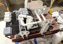
So here's a shot showing progress to date. Notice how the pipes are sagging. These are supported by the ceiling hangers. I'm going fab some hangers out of brass that will hang from that little bit of ceiling from the stair entry.

And look at the dent I'm making in that massive parts pile. This is all that's left. Could be done in two work sessions, but probably a bit longer for touch up work.

Stay tuned!
I found the sweet spot in positioning the hp and LP turbines so the cross over pipe was more or less centered on its flanges. This was glued with epoxy. Main steam was installed and it's split feed glued into the input flanges on the HP throttle valve body. There is a lead wire coming down from this pipe for the LEDs that lie on its bottom.
Here's the wiring disappearing beneath the floor.
It was time to get the fore catwalks in that surround the LP turbine. There's a very narrow walk that lies between the two turbines and I was pleased that after fussing with the location of the LP turbine, the walk fit nicely. The larger catwalk that wraps around the turbine also was touch and go. The angular vertical braces in the front are not actually touching the LP support frame. I may be able to fix that so it looks a little better.
Next up was the main air ejector which glues to the front bulkhead. The vacuum pipe was a two-piece affair that had to locate somewhere under the main condenser. Took some fancy maneuvering to get all that cooperating. The steam inlet line ties in above to the main steam. This was adhered with epoxy and some med CA.
With the MAE in I added two more pipes that feed off of main steam, the astern steam lines. In the 1:1 model, they follow a curvy route, most likely for expansion with the 800 degree steam within. I attempted to duplicate this path.
The port flooring began with the front part. I had to stop there becase I need to install the turbogenerator unit and the port #4 prop shaft. Then the remaing floor goes in. I had to make some relief cuts on the walk in front of the lube pumps to clear the TG columns.
So here's a shot showing progress to date. Notice how the pipes are sagging. These are supported by the ceiling hangers. I'm going fab some hangers out of brass that will hang from that little bit of ceiling from the stair entry.
And look at the dent I'm making in that massive parts pile. This is all that's left. Could be done in two work sessions, but probably a bit longer for touch up work.
Stay tuned!
Attachments
Vic Balshaw
Major General
Great work, it's all looking very complex. 
Great work so far!
- Thread starter
- #469
Builder 2010
Staff Sergeant
It's insanely complex. It's gotten very difficult to see into the dark spaces to glue some things in. For example: after spending 1/2 hour to finally get all the pins on all the legs into their respective holes, I couldn't reach in to add CA to the legs closest to the MRG. No matter how I attempted it, I a) I couldn't see them, and b) even if I could, I had no way to get a glue applicator into the right spot. So those legs are not glued, but enough of them are to secure the unit… I hope. The other challenge was the clearances are so tight that things like pipe runs are bending around obstacles that, on the drawings, had clearance. The #4 prop shaft was very tight with the TG columns and the added leg to the forwad platform is being pushed to the starboard by the shaft. I may remove that tilted column and cantilever somethig from the electrical mezzanine. Those H-columns aren't on the real ship. That platform is supported by the fore bulkhead which is cutaway on the model.
I cobbled together somekind of pipe hanger for the main steam line to raise it level. what I had envisioned didn't account for the difficulty of working on the real pipe in its difficult location. I used some brass strip left over photoetched fret. Ironically, this particular piece was left over from when I built my Missouri in 2012. After cutting the material, I bent the overlap area and drilled a 25 gauge wire hole. I inserted a piece of #25 wire across the flats used a Vice Grip to squash one end so it would no longer pass through the hole. I formed a shaft and eye of the same wire and soldered this to the cross wire (while the wire was out of the holes). I then took it to the pipe and held the two flats together with a hemostat. I drilled a 32 gauge hole in the styrene floor of the entry and inserted the wire from underneath. I used a dental mirror to see where the wire was going. That wasn't fun!

I pulled the two ends together with another forceps getting the cross wire into the other hole and then, using the same Vice Grip squashed the other end captivating the wire. I was impossible to solder in that space. After pulling the pipe up to the desired height, I bent the wiring sticking out of the hole. I made a little brass plate with a hole that was placed over the wire. I would have liked to solder the plate to the, but it's on Styrene which melts at solder temperature. I'm going to use epoxy and trim the wire shorter. For the smaller astern steam line (also sagging) I used some aluminum wire to make a hanger, also threaded through a hole. This too will be epoxied. I held off with the epoxy until I have other things to use it on.

I attached the main condensate pump exhaust line to the fore side of the main condenser. This line had to thread its way behing the main air ejector. It made it, but it's a bit askew.

I realized that I had better get that prop shaft in. It was a very tight fit and put some stress on the styrene bulkheads fore and aft due to pressure from one of the metal TG columns. I new it was a close fit, but I didn't anticipate that it was contacting it. Everything is solid. And then was able to install the fore platform with the tilted column. I was planning on using epoxy, but the fit was so finicky that it would have been a mess if I touched other surfaces while maneuvering it into place.


I was just at the point to install the steam line to the TGs when I ran out of time. Tomorrow I will install that line and the last pipe that is the steam line to the main condensated pump. Once that's in place, the last floor pieces go in; one aft of the port lower floor and the other between the MRG and the TG platform. I have to glue down the bridge over the torque tubes and it's respective ladders. And then the last couple of ladders on the port side including the long one that runs from the upper floor to lower betwee the TGs and MRG. And then the very last thing that goes in is the electrical decks. AND THE MODEL WILL BE BUILT. I will be doing touch up painting and minor corrections of any gratings that were damaged during assembly.
Then I will finish up the case with the locking straps so I can install the case and tip it on the side to tie in the LED wiring. I also have to repair the damage I did to the wood base.
And then model will be ready for delivery.
Delivery will be early November I think.
I cobbled together somekind of pipe hanger for the main steam line to raise it level. what I had envisioned didn't account for the difficulty of working on the real pipe in its difficult location. I used some brass strip left over photoetched fret. Ironically, this particular piece was left over from when I built my Missouri in 2012. After cutting the material, I bent the overlap area and drilled a 25 gauge wire hole. I inserted a piece of #25 wire across the flats used a Vice Grip to squash one end so it would no longer pass through the hole. I formed a shaft and eye of the same wire and soldered this to the cross wire (while the wire was out of the holes). I then took it to the pipe and held the two flats together with a hemostat. I drilled a 32 gauge hole in the styrene floor of the entry and inserted the wire from underneath. I used a dental mirror to see where the wire was going. That wasn't fun!
I pulled the two ends together with another forceps getting the cross wire into the other hole and then, using the same Vice Grip squashed the other end captivating the wire. I was impossible to solder in that space. After pulling the pipe up to the desired height, I bent the wiring sticking out of the hole. I made a little brass plate with a hole that was placed over the wire. I would have liked to solder the plate to the, but it's on Styrene which melts at solder temperature. I'm going to use epoxy and trim the wire shorter. For the smaller astern steam line (also sagging) I used some aluminum wire to make a hanger, also threaded through a hole. This too will be epoxied. I held off with the epoxy until I have other things to use it on.
I attached the main condensate pump exhaust line to the fore side of the main condenser. This line had to thread its way behing the main air ejector. It made it, but it's a bit askew.
I realized that I had better get that prop shaft in. It was a very tight fit and put some stress on the styrene bulkheads fore and aft due to pressure from one of the metal TG columns. I new it was a close fit, but I didn't anticipate that it was contacting it. Everything is solid. And then was able to install the fore platform with the tilted column. I was planning on using epoxy, but the fit was so finicky that it would have been a mess if I touched other surfaces while maneuvering it into place.
I was just at the point to install the steam line to the TGs when I ran out of time. Tomorrow I will install that line and the last pipe that is the steam line to the main condensated pump. Once that's in place, the last floor pieces go in; one aft of the port lower floor and the other between the MRG and the TG platform. I have to glue down the bridge over the torque tubes and it's respective ladders. And then the last couple of ladders on the port side including the long one that runs from the upper floor to lower betwee the TGs and MRG. And then the very last thing that goes in is the electrical decks. AND THE MODEL WILL BE BUILT. I will be doing touch up painting and minor corrections of any gratings that were damaged during assembly.
Then I will finish up the case with the locking straps so I can install the case and tip it on the side to tie in the LED wiring. I also have to repair the damage I did to the wood base.
And then model will be ready for delivery.
Delivery will be early November I think.
Vic Balshaw
Major General

N4521U
Plastic Pirate
Absolute Stellar work. I salute you mate!
Jamoliva
Airman 1st Class
Wow!
- Thread starter
- #474
Builder 2010
Staff Sergeant
The end is Nigh… Got more stuff in today with only the electrical loft and the auxiliary air ejectors to install. I also had to modify the drawings on two ladders. I reduced a 5-step to 4 and lengthened a 9-step to 10. These new printings are the result of my vertical errors. X-Y axis errors, while present, didn't require reprintings. The Z-axis error of drawing and building the TG asembly about a 1 scale foot to tall caused my catwalks to not integrate as I drew them and made the ladders not fit in certain locations. Ryan would probably notice the differences, but the average viewer shouldl be so overwhelmed by the complexity that they shouldn't notice.
Some things added were very noticeable, like the installation of the main gauge panel and phone booth, (sorry about the depth of field issues)

the remaing lower level floor,

and the grating platform between the MRG and TGs.

It was this pieces elevation that caused the ladder problem. The tall one that went from this level to the lower one didn't reach the floor, and the one from the entry catwalk was too tall by one step. I epoxied the bridge in and its stair on the starboard side, but the port side needed some floor to land on so I epoxied a bit of grating to the ladder feet and next seesion will attach that grating to the rest of the catwalk.
I also installed the TG steam line and header into the main steam with a 3/64 brass pin and epoxy. I held it with tape until it cured. I then secured the lines into the turbos, also with epoxy. And then installed last steam pipe from the main header to the input side of the main condensate pump. There was slight misalignment in the x axis direction so the pipe is not plumb. I suppose I could redrawn and reprinted, but frankly, I'm wanting to finish the build. A lot of these slight misalignments are the result of the decision to draw and print all the piping instead of fitting it on the model after the operating units were in place. That too would have been very difficult as reaching into the model to measure and place things is getting impossible in certain areas. I dropped one of the small ladder units down between the LP turbine and MRG and had to use a wire with a hook on it to fish it out. Otherwise, I would have had to turn the model upside down and shaken it. And that ain't gonna happen! For all the piping to end up perfectly square would required every unit to be placed precisely as they were drawn, and I don't know how I could have pulled that off.

I put some Milliputt epoxy putty on the transition from the larger header to the smaller MCP pipe to give it a better look. I will finish sand it after it's cured fully.

Installing the aux air ejectors shouldn't present problems, nor should the installation of the electrical loft, but it will have to wait a couple of weeks. Tomorrow morning we're leaving for a 10-day vacation to France, staring in the Burgundy Region and ending in Paris. My wife and I have been to Paris many times, mostly when we were living in Germany and I was working for Henkel. We enjoy travel and like France. The ladders are finished printing, but they're going to hang draining the Machine until I get back to work. Now some might ask, what's a guy who spends his time doing what he loves building creations need with a vacation. Heck, everyday is a vacation. That's true, but my wife doesn't have my level of creative engagement and it's good to have a change of scenery to recharge the batteries.
So, here's what's left.

It's hard to me to believe that all this;

Magically, turns into this….


And the artist's (Me) rendering done long ago when the drawings were just about finalized.

Within a week after we return the model should be done, lit and the case finalized. I will be photographing with a higher production value than the above. At the start, August 2024, I predicted it would take about 14 months to complete. We're really close to that estimate.
Some things added were very noticeable, like the installation of the main gauge panel and phone booth, (sorry about the depth of field issues)
the remaing lower level floor,
and the grating platform between the MRG and TGs.
It was this pieces elevation that caused the ladder problem. The tall one that went from this level to the lower one didn't reach the floor, and the one from the entry catwalk was too tall by one step. I epoxied the bridge in and its stair on the starboard side, but the port side needed some floor to land on so I epoxied a bit of grating to the ladder feet and next seesion will attach that grating to the rest of the catwalk.
I also installed the TG steam line and header into the main steam with a 3/64 brass pin and epoxy. I held it with tape until it cured. I then secured the lines into the turbos, also with epoxy. And then installed last steam pipe from the main header to the input side of the main condensate pump. There was slight misalignment in the x axis direction so the pipe is not plumb. I suppose I could redrawn and reprinted, but frankly, I'm wanting to finish the build. A lot of these slight misalignments are the result of the decision to draw and print all the piping instead of fitting it on the model after the operating units were in place. That too would have been very difficult as reaching into the model to measure and place things is getting impossible in certain areas. I dropped one of the small ladder units down between the LP turbine and MRG and had to use a wire with a hook on it to fish it out. Otherwise, I would have had to turn the model upside down and shaken it. And that ain't gonna happen! For all the piping to end up perfectly square would required every unit to be placed precisely as they were drawn, and I don't know how I could have pulled that off.
I put some Milliputt epoxy putty on the transition from the larger header to the smaller MCP pipe to give it a better look. I will finish sand it after it's cured fully.
Installing the aux air ejectors shouldn't present problems, nor should the installation of the electrical loft, but it will have to wait a couple of weeks. Tomorrow morning we're leaving for a 10-day vacation to France, staring in the Burgundy Region and ending in Paris. My wife and I have been to Paris many times, mostly when we were living in Germany and I was working for Henkel. We enjoy travel and like France. The ladders are finished printing, but they're going to hang draining the Machine until I get back to work. Now some might ask, what's a guy who spends his time doing what he loves building creations need with a vacation. Heck, everyday is a vacation. That's true, but my wife doesn't have my level of creative engagement and it's good to have a change of scenery to recharge the batteries.
So, here's what's left.
It's hard to me to believe that all this;
Magically, turns into this….
And the artist's (Me) rendering done long ago when the drawings were just about finalized.
Within a week after we return the model should be done, lit and the case finalized. I will be photographing with a higher production value than the above. At the start, August 2024, I predicted it would take about 14 months to complete. We're really close to that estimate.
Vic Balshaw
Major General
I do believe this is more complex than anything you have done to date. It's a winner.
Incredible, a pleasure to see this come together.
SaparotRob
Unter Gemeine Geschwader Murmeltier XIII
Wow!
special ed
1st Lieutenant
- 6,602
- May 13, 2018
A possible interesting aside. In reference to your calling weights gravity clamps, I spent yesterday morning cleaning more angle iron with the wire wheel on my grinder, watched from a distance by my neighbor. He often looks in on my piddly projects and asks questions. By afternoon, I was grinding the cutoff surfaces ready to paint, so Mr. neighbor wanders over and asks what I am making. When I replied, "Gravity clamps." He asked, "How do they work?" I had him, thanks to your nomenclature. I took several pieces of wood, stacked them and put the angle stock on top. He stood silent a moment thinking, then quietly walked home.
Users who are viewing this thread
Total: 1 (members: 0, guests: 1)