1/72 A&A Models Northrop F-15 Reporter (aka photo-recon P-61 Black Widow) (3 Viewers)

Ad: This forum contains affiliate links to products on Amazon and eBay. More information in Terms and rules

Snautzer01, always good to see more pictures! One that I found particularly interesting is the P-61 with canvas covers over all three tires. I'm used to seeing canopy covers both in photos and in manuals, but I don't recall seeing this before.
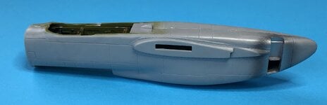
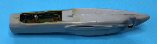
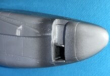
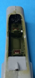
If I ever feel tired and want to do a quick build, I suppose adding canopy covers, intake covers, and wheel covers would really speed things up!
 
The pilot seat had a folded armor plate. It was wide at the shoulders and narrow for the head, where it had a padded headrest.
 

Attachments

  • IMG_6239.jpg
    IMG_6239.jpg
    266.1 KB · Views: 1
  • IMG_6242.jpg
    IMG_6242.jpg
    195.4 KB · Views: 2
  • IMG_6243.jpg
    IMG_6243.jpg
    329.1 KB · Views: 2
If you are modeling the F-15 with the main gear doors closed, you can glue in the shorter (outboard) door before the landing gear, as shown in the first photo.
Of course, first you have to remove forward section of the door, first.
The second photo is to show that you need to make a small notch on the longer (inboard) door. If you glue that door on, you can no longer install the landing gear. Or at least you will need to figure out how to work it in (you perhaps could notch out the hole that the gear goes into, but I have not verified that myself and it will make it harder to properly align the gear).
The way the main gear doors work is common with the P-61B/C/D/E.
 

Attachments

  • IMG_6240.jpg
    IMG_6240.jpg
    224.2 KB · Views: 1
  • IMG_6241.jpg
    IMG_6241.jpg
    231.9 KB · Views: 2
Got the fuselage put together. You have to choose between displaying the canopy either open or closed. Unless you want to get really fancy and come up with an actual sliding canopy mechanism! :)
I'm sure somebody will. My hat is off to them!
When the canopy is closed, you use this square insert behind the navigator.
If you want to display the canopy open, there is a flat square insert that you insert in that same place. Then there is a smaller rectangular piece with the bump that attaches to the canopy itself. I believe that when the canopy is being opened, the back end first pops up, then it slides back. I haven't found any information on how the canopy is actuated. Being so large I would expect it to be hydraulically actuated - anybody know?
 

Attachments

  • IMG_E6254.jpg
    IMG_E6254.jpg
    346.9 KB · Views: 1
  • IMG_E6253.jpg
    IMG_E6253.jpg
    341.2 KB · Views: 1
As expected, you can barely see anything in the aft compartment. Which is just as well since I just took my best guess and put some radio equipment in there. Then I found a drawing in Kolln's book that shows exactly what was installed there! As it turns out, it probably looks about right after all.
 

Attachments

  • IMG_E6255.jpg
    IMG_E6255.jpg
    543.5 KB · Views: 1
So far, it still looks pretty representative of a Reporter.
There are a couple of problems with the camera nose, though.
Doyle's book has a drawing that shows the XF-15 Prototype with a small rectangular window and the later turbocharged F-15 aircraft (XF-15A and F-15A) with a larger trapezoidal window. After reviewing every picture I could find, I have come to a different conclusion.
It looks like every Reporter (XF-15, XF-15A, F-15A) actually had a small rectangular window on the port side and a larger trapezoidal window on the starboard side.
The shape of the starboard trapezoidal window was changed for the production F-15As, though. For the XF-15 and XF-15A, the diagonal side was to the front. For the production F-15As, however, the diagonal side was to the aft.
The A&A F-15 Reporter model is more like the first two prototypes as it has the diagonal side to the front. Unfortunately, they did this on the port side, too, so that will need to be filled in a bit. Fortunately, not a big job.
The other problem with the nose is the shape. There were two optically flat camera windows on the bottom surface and the nose should indeed conform to them, but A&A chose to extend the flat surface too far forward. On the real aircraft, the bottom surface starts to transition to being rounded immediately forward of the windows. That corner needs to be rounded off a bit, which may also fix another shape problem. On the real aircraft, the starboard side window has a hemispherical flat in front of it because the side of the nose is actually rounded. A&A made the side of the nose pretty flat already so you don't get that feature. Once you round the bottom corner you can also probably add a little curvature to the side of the nose, then file it flat in front of the window. I'll let you know how that goes!
 

Attachments

  • IMG_E6262.jpg
    IMG_E6262.jpg
    331.5 KB · Views: 1
  • IMG_E6259.jpg
    IMG_E6259.jpg
    249.4 KB · Views: 1
  • IMG_E6258.jpg
    IMG_E6258.jpg
    249.4 KB · Views: 1
Regarding references, I am mostly relying on two books plus whatever I can find on the web.
Squadron's "P-61 Black Widow In Action" by David Doyle, and
Specialty Press' "Northrop's Night Hunter P-61 Black Widow" by Jeff Kolln.
These are both excellent books and I would highly recommend both of them. Lots of great photos and some very interesting histories.
 
Reshaping the front of the nose made it look a lot more like the real thing. I left it unsanded so that you can see where material needs to be removed.
I rounded the cross-section, made the nose a little less blunt, made the front camera face more vertical and marked where the front window opening should be expanded to accommodate two separate trapezoidal windows. The profile looks a lot better now.
This is another case where the A&A model actually represents the XF-15A rather than the F-15A. That step in front of the aft bottom window does not exist on the production F-15A. They changed that transition to a ramp instead of a step.
Now I need to shrink the port window down to a small rectangle and it also looks like the starboard window is a bit too tall, so I will fill part of it in, too.
I'm going to use one piece of clear plastic for the two bottom trapezoidal windows and then mask them off as needed. The hole seems to be a little too big, so that will solve this problem (and will put the glue joint underneath the paint where it belongs!)
 

Attachments

  • IMG_E6268.jpg
    IMG_E6268.jpg
    2.3 MB · Views: 1
  • IMG_E6269.jpg
    IMG_E6269.jpg
    544.8 KB · Views: 1
  • IMG_E6270.jpg
    IMG_E6270.jpg
    123.2 KB · Views: 1
  • IMG_E6271.jpg
    IMG_E6271.jpg
    151.4 KB · Views: 1
  • IMG_E6272.jpg
    IMG_E6272.jpg
    212 KB · Views: 1
  • IMG_E6273.jpg
    IMG_E6273.jpg
    215.7 KB · Views: 1
Here's another photo of the original XF-15 and its camera nose. Note the unusual transition from the curved sheet metal to the aft edge of the port side window.
 

Attachments

  • XF-15 Reporter camera nose.jpg
    XF-15 Reporter camera nose.jpg
    78.2 KB · Views: 0

Users who are viewing this thread

  • Back