
Simon Thomas
Senior Airman
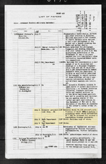
From Technical data digest, U.S. Army air forces v.7 no.24 1941 Dec 15
I found a copy:
Last edited:

Follow along with the video below to see how to install our site as a web app on your home screen.
Note: This feature may not be available in some browsers.
This is probably referring to what is usually called deflection plate. It usually consisted of an increased thickness of the skin plating, but it could also be a significantly thicker and separate aluminum plate fastened over a section of the fuselage skin. This was usually to deflect tha projectile away from a specific area or in order to start the projectile tumbling before it reached the interior armour - thereby increasing the effectiveness of the armour plate. Below is an example layout on a F4U. Note that the thickness varied depending on the aircraft and location, and whether it took the place of the original skin panel or if it was applied over the already existing skin. Sometimes it would simply be 2 skin panel panels applied one over the other, usually it was a thicker replacement panel (10 SWG / 0.128" for example) at a minimum, but depending on the airframe some of the plating applied over the skin panels it could reach upto 3/8". I think the thickness of the large deflection plate in front of the cockpit on the F4U diagram below was 3/16".AHT also mentions a section of armour on both sides of the fuselage behind the pilot, which is not displayed in the above image. Interestingly the top-down image seems to indicate armoured glass above the pilot as well. EDIT: AHT also does not specify the thickness of the pilot's seat armour, which it mentions consisted of a plate aft of the seat. 4.25 mm, if accurate, is remarkably thin!
The hashmarked square that appears to be over the cockpit is the area the seat armour would appear to occupy if you look at an X-ray of the airframe from the top down, in a similar manner to how the pilot's seat bottom armour appears in the F4U diagram above.Interestingly the top-down image seems to indicate armoured glass above the pilot as well. EDIT: AHT also does not specify the thickness of the pilot's seat armour, which it mentions consisted of a plate aft of the seat. 4.25 mm, if accurate, is remarkably thin!

From Technical data digest, U.S. Army air forces v.7 no.24 1941 Dec 15
https://catalog.hathitrust.org/Record/002138627 I found a copy:
Book Library
Possibly this would be of some help. It is the index for most(?) of the aeronautical related technical documents held at Wright Field - which may be under the NASM umbrella of responsibility now. It is word searchable, and there are lots of documents listed under Brewster and F2A - maybe other designations and/or subject headings - I have not had time to go through it in detail yet. Unfortunately, most are not digitized yet, but more are being processed every day.
re
This is probably referring to what is usually called deflection plate. It usually consisted of an increased thickness of the skin plating, but it could also be a significantly thicker and separate aluminum plate fastened over a section of the fuselage skin. This was usually to deflect tha projectile away from a specific area of in order to start the projectile tumbling before it reached the interior armour - thereby increasing the effectiveness of the armour plate. Below is an example layout on a F4U. Note that the thickness varied depending on the aircraft and location, and whether it took the place of the original skin panel or if it was applied over the already existing skin. Sometime it would simply be 2 skin panel panels applied one over the other, usually it was a thicker replacement panel (10 SWG / 0.128" for example) at a minimum, but depending on the airframe some of the plating applied over the skin panels it could reach upto 3/8". I think the thickness of the large deflection plate in front of the cockpit on the F4U diagram below was 3/16".
View attachment 890268
re
The hashmarked square that appears to be over the cockpit is the area the seat armour would appear to occupy if you look at an X-ray of the airframe from the top down, in a similar manner to how the pilot's seat bottom armour appears in the F4U diagram above.
| Maker | Brewster | |
| Name | Buffalo | |
| Type | 1 Seat Fighter | |
| Engine | Number | 1 |
| Make | Cyclone G105A | |
| Cooling | Air | |
| Power | Horse Power | 800 |
| At Height (feet) | 17,100 | |
| Size | Span (feet, inches) | 35' |
| Length (feet, inches) | 26' | |
| Height (feet, inches) | 12' | |
| Wing Area (square feet) | 178 (nett) | |
| Men | Crew | 1 |
| Armament | Forward Fuselage (a) | Two 0.5 inch |
| Forward Wings (b) | Two 0.5 inch | |
| Rounds Per Machine Gun | 250(a), 500(b) | |
| Weight | Tare (pounds) | 4,495 |
| Normal | Weight (pounds) | 6,272 |
| Take Off (Over 50 ft) (Yards) | 190 (Ground) | |
| Climb to Height (feet) | 15,000 | |
| Climb to Height Time (Mins) | 6.3 | |
| Service Ceiling (Feet) | 31,000 | |
| Maximum Speed (m.p.h) | 313 | |
| Max Speed Height (Feet) | 18,500 | |
| Cruising Speed (m.p.h) | 255 | |
| Cruise Speed Height | 15,000 | |
| Range (15 mins allowance) Miles | 520 | |
| Endurance (15 mins allowance) Hours | 1.78 | |
| Fuel for range, gallons | 66.5 | |
| Fuel for allowance, gallons | 25.5 | |
| Fuel (Total, Gallons) | 92 | |
| Extended | Overload Weight (pounds) (Maximum Fuel) | 6,588 |
| Maximum Fuel Capacity (Gallons) | 133 | |
| Service Ceiling | 30,000 | |
| Fast | Speed (m.p.h) | 255 |
| Height (feet) | 15,000 | |
| Range (15 mins allowance) Miles | 840 | |
| Endurance (15 mins allowance) Hours | 3.28 | |
| Fuel for range, gallons | 107.5 | |
| Fuel for allowance, gallons | 25.5 | |
| Fuel (Total, Gallons) | 133 | |
| Economic | Speed (m.p.h) | 180 |
| Height (feet) | 15,000 | |
| Range (15 mins allowance) Miles | 900 | |
| Endurance (15 mins allowance) Hours | 4.9 | |
| Fuel for range, gallons | 101 | |
| Fuel for allowance, gallons | 32 | |
| Fuel (Total, Gallons) | 133 |

When the British were examining the initial Buffalos they noted the US armour plate in place, but also said this would be replaced by British armour. I can't say for sure why, but I know they were suspicious of the Mohawk's low-quality armour plate when examining the first examples of those.
4-mm seat amour plate would match what was in place for the early-war Hurricane and Spitfire.
The USN Take, from Naval Aircraft, Record of Acceptances 1935-1946 Bureau of Aeronautics, Navy Department, Washington DC, NAVAER 15838
1 XF2A USN (Dec 1938), approved name Buffalo
92 F2A Holland, (72 Mar-Jun-41, 20 Jan-Apr 42), Model 339D, approved name Brit. Buffalo
11 F2A-1 USN (May-Dec 39), approved name Buffalo
44 F2A-1 Finland (Dec? 1939 - Feb 40), Model 239, approved name Buffalo
43 F2A-2 USN (Sep-Nov 40 plus 1 in Jan 41), approved name Buffalo
40 F2A-2 Belgium (most to Britain) (Apr-Jul 40), Model 339, approved name Buffalo
170 F2A-2 Britain (Dec 40 - May-41), Model 339E, approved name Buffalo
108 F2A-3 USN, approved name Buffalo
509 Total

 FulmenTheFinn
 ....
Performance Tables of British Service Aircraft, Air Publication 1746, dated August 1939 but data includes 1940/41 aircraft. The ranges of fighters are shown as ranges at maximum economic cruising power on the fuel available, after deducting fuel used in 15 minutes at maximum power at sea level. This allowance is for warming up and climbing to operational height.
Maker Brewster Name Buffalo Type 1 Seat Fighter Engine Number Make Cyclone G105A Cooling Air Power Horse Power At Height (feet) Size Span (feet, inches) 35' Length (feet, inches) 26' Height (feet, inches) 12' Wing Area (square feet) 178 (nett) Men Crew Armament Forward Fuselage (a) Two 0.5 inch Forward Wings (b) Two 0.5 inch Rounds Per Machine Gun 250(a), 500(b) Weight Tare (pounds) Normal Weight (pounds) Take Off (Over 50 ft) (Yards) 190 (Ground) Climb to Height (feet) Climb to Height Time (Mins) Service Ceiling (Feet) Maximum Speed (m.p.h) Max Speed Height (Feet) Cruising Speed (m.p.h) Cruise Speed Height Range (15 mins allowance) Miles Endurance (15 mins allowance) Hours Fuel for range, gallons Fuel for allowance, gallons Fuel (Total, Gallons) Extended Overload Weight (pounds) (Maximum Fuel) Maximum Fuel Capacity (Gallons) Service Ceiling Fast Speed (m.p.h) Height (feet) Range (15 mins allowance) Miles Endurance (15 mins allowance) Hours Fuel for range, gallons Fuel for allowance, gallons Fuel (Total, Gallons) Economic Speed (m.p.h) Height (feet) Range (15 mins allowance) Miles Endurance (15 mins allowance) Hours Fuel for range, gallons Fuel for allowance, gallons Fuel (Total, Gallons)
My info may be wrong, but in my notes for the first armour installations on the Hurricane and Spitfire I have the primary armour behind the seat and head being a nominal 1/4" (often stated as 6mm but actually coming in at 6.25-6.4mm). The later additions of the lower/under-seat and leg armour are listed as a nominal 5/32" (4mm).. . . 4-mm seat amour plate would match what was in place for the early-war Hurricane and Spitfire.
Excellent, Finnish test flights, the aircraft used was the BW-366, one of the better ones. Max speed was 428 km/h at sea level and 480 km/h at just under 5000 meters. The Finns usually made a compression correction to their speed test results.This thread is going for three years and 290+ posts but real inspiration for my post is the spec sheet posted by Geoffrey Sinclair yesterday.
I did try a best estimate model of Brewster fighters couple of years ago. While F2A-2 and -3 are reasonably well documented (NAVAER spec sheets available at least), the earlier durect-drive Brewster 239 variants are not well covered.
There is what I got performance-wise from my model of Brewster 239 and F2A-3.
Best regards,
Yavor
View attachment 890426
View attachment 890427
View attachment 890428
View attachment 890429
View attachment 890430
In metric units, high gear, 4854.5 m, 34" Hg boost, the maximum speed on the Brewster 239 graph is 478.5 km/h.... Finnish test flights, the aircraft used was the BW-366, one of the better ones. Max speed was 428 km/h at sea level and 480 km/h at just under 5000 meters. The Finns usually made a compression correction to their speed test results.
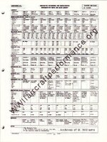
You have an interesting set of data. I do not think the Brewster performance will be on the same level with a two-blade wooden propeller, or the two-blade AW-1 propeller from an I-16, even equipped with an M-63 engine. With a blade tip speed well into supersonic range the aircraft is going to remain below 500 km/h maximum level speed.Here's an example of what I have right now for fully loaded Brewsters:
...
My info may be wrong, but in my notes for the first armour installations on the Hurricane and Spitfire I have the primary armour behind the seat and head being a nominal 1/4" (often stated as 6mm but actually coming in at 6.25-6.4mm). The later additions of the lower/under-seat and leg armour are listed as a nominal 5/32" (4mm).
HiI have:
6 mm plate for the pilot's head armour
4 mm plate for the pilot's seat back
6 mm plate for the seat extension (legs)
8 swg dural for the seat bottom (works out to about 4 mm)
As we've been saying, nominal thickness. Just as I was looking the above figures up and saw Orfordness measurements of a Spitfire back plate at 4.4 mm and Hurricane back plates at 4.3 mm and 4.5 mm.
| Month | Total | USN | Finland | Belgium | USN | Britain | NEI | USN |
| Month | Model | F2A-1 | 239 | 339 | F2A-2 | 339E | 339D | F2A-3 |
Jun-39 | 1 | 1 | ||||||
Jul-39 | 1 | 1 | ||||||
Aug-39 | 1 | 1 | ||||||
Sep-39 | 0 | |||||||
Oct-39 | 0 | |||||||
Nov-39 | 2 | 2 | ||||||
Dec-39 | 12 | 6 | 6 | |||||
Jan-40 | 24 | 24 | ||||||
Feb-40 | 14 | 14 | ||||||
Mar-40 | 0 | |||||||
Apr-40 | 1 | 1 | ||||||
May-40 | 8 | 8 | ||||||
Jun-40 | 22 | 22 | ||||||
Jul-40 | 9 | 9 | ||||||
Aug-40 | 0 | |||||||
Sep-40 | 6 | 6 | ||||||
Oct-40 | 20 | 20 | ||||||
Nov-40 | 16 | 16 | ||||||
Dec-40 | 40 | 40 | ||||||
Jan-41 | 43 | 1 | 42 | |||||
Feb-41 | 18 | 18 | ||||||
Mar-41 | 36 | 18 | 18 | |||||
Apr-41 | 46 | 36 | 10 | |||||
May-41 | 43 | 16 | 27 | |||||
Jun-41 | 17 | 17 | ||||||
Jul-41 | 1 | 1 | ||||||
Aug-41 | 24 | 24 | ||||||
Sep-41 | 41 | 41 | ||||||
Oct-41 | 23 | 23 | ||||||
Nov-41 | 9 | 9 | ||||||
Dec-41 | 10 | 10 | ||||||
Jan-42 | 10 | 10 | ||||||
Feb-42 | 0 | |||||||
Mar-42 | 1 | 1 | ||||||
Apr-42 | 9 | 9 | ||||||
| Total | 508 | 11 | 44 | 40 | 43 | 170 | 92 | 108 |


