eBay: Plane gear the meters, dails levers radios etc Technik (1 Viewer)

Ad: This forum contains affiliate links to products on Amazon and eBay. More information in Terms and rules

Yes, thanks for posting,
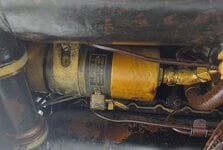
These 9-14501 Verstellgerate are interesting parts of the VDM Propeller system. The unit is basically a Bosch designed 24V reversable DC motor that is coupled to a limiting switch geartrain at one end, with a direct power-drive to the VDM Propeller system at the other end. Bosch must have worked closely with VDM on this and it was probably done under contract to VDM. The end with the stamped, "Warning Do not turn", is the connection to the prop-pitch indicator and is linked into the lightweight limit-stops geartrain. The drive end marked "Luftschraube" is the power-drive to the prop pitch changing mechanism. You see it has a special type nut with internal ferrule that retains the free-floating rigid shaft used on these units fitted to the DB 605 and DB 601 E/F. Earlier versions on the DB 601 A/N still used a flexible drivecable and did not have the special retaining nut because it used the screw-on cable fitting. The unit here with the retaining nuts on both ends should only have 1 nut, fitted at the Luftschraube end, the other nut at the gear drive end is incorrect and should be fitted on the other unit at the Luftschraube end, so that both units have a drive retaining nut at their Luftschraube end. The markings stamped at the geartrain endstop cover are E and A/B. The E is for adjusting the Endmoment electrical limit stop that defines how coarse towards the feathered position the motor will run before stopping, this depends on aircraft type. The A/B setting is the VDM system operating definition that is used to set-up the system for either Left or Right handed propeller rotation. The Gerate code sub-group like E or G-3 principally indicates minor revisions of production. However, some versions incorporated or deleted the electrical pitch indication system circuitry.
This unit is almost entirely linked to the later Bf 109 E, all Bf 109 F,G,K, most Bf 110 and most other aircraft fitted with DB 601, DB 605 after 1940.

Eng
 

Attachments

  • Motor_for_VDM_Prop.pdf
    1.2 MB · Views: 3
Hi Tony,
Thanks for your pic of the VDM/BOSCH prop pitch motor on #101.
The illustration is useful and it includes the details about the A/B switch, it says: " Setting A for Right-hand Tractor and Left-hand Pusher Propeller. Setting B for Right-hand Pusher and Left-hand Tractor Propeller". This convention maintained the integrity of the VDM pitch indication system, whereby the Pitch indicating "clock" moved anti-clockwise for increasing blade pitch and clockwise for decreasing blade pitch. Also, all aircraft used a Take-off setting of 12.00 on the pitch "clock".
There are many more tech details for anyone who needs to use one of these systems. Unfortunately, a Wartime translation/description of the system by the U.S. "T-2" dept incorrectly stated that the pitch "clock" moved the other way, ie clockwise for increasing blade pitch. This mistake was very regrettable as that English language translation/description is widely read today. In fact, if the propeller set-up and function is done correctly, it is found that the incorrect description of the indication function is obvious. However, this mistake has caused much confusion!

Eng
 

Attachments

  • BF109_Prop_Pitch_Motor_DB605.jpg
    BF109_Prop_Pitch_Motor_DB605.jpg
    503 KB · Views: 3
A nice pic from Tony of the 9-14501 Propeller pitch motor fitted to the DB 605 A in a Bf 109 G. You can see that it fits into the V between intake manifolds, at the front end of the engine. The round motor sits on a rubber-mounted magnesium cradle and it is held tight with the steel clamping band that is visible around the motor.
The pitch indicator drive is visible at the right end of the pic. At first sight, you might think "that Eng Bloke said there should not be a big nut on that end!" In fact, the nut seen here is the integral securing nut of the 45 degree angled drive adapter for the cockpit pitch indicator drive cable. This adapter is used in some installations, there are also 90 degree angled drives used here, and in fact the straight flexible drive cable will also fit without an adapter, so you may see all these variations in the attachment of the flexible pitch instrument drive cable.

Eng
 
Last edited:
FK38 Kompass me109 bf109 fw190 ju88 ju87 Fl.23233 Fl23233

View attachment 740566

View attachment 740567

Fl 23233 Führerkompass FK 38

1710849098844.png


1710849136238.png


1710849112873.png


As an eBay Associate we earn from qualifying purchases.
CP-6/APQ-13 RADAR H2X MICKEY BOMBER B-29 WESTERN ELECTRIC

1711020755769.png


1711020781300.png


1711020789729.png


1711020816432.png


1711020826965.png


1711020835549.png


As an eBay Associate we earn from qualifying purchases.
CP-6/APQ-13 RADAR H2X MICKEY BOMBER B-29 WESTERN ELECTRIC

View attachment 769744

View attachment 769745

View attachment 769746

View attachment 769747

View attachment 769748

View attachment 769749

Does anyone know how much total weight the radio gear tallied on these, or any large, late war bomber?
 
As an eBay Associate we earn from qualifying purchases.
RT-7/APN-1 FREQUENCY MODULATED ALTIMETER RECEIVER

1711189839845.png


1711189863324.png


As an eBay Associate we earn from qualifying purchases.

Users who are viewing this thread

Back