Henk
Master Sergeant
Henk
Follow along with the video below to see how to install our site as a web app on your home screen.
Note: This feature may not be available in some browsers.
Ad: This forum contains affiliate links to products on Amazon and eBay. More information in Terms and rules
JardaJarda Rankl said:And that exactly is the thing. I´ve been interested in WWII for more than 30 years and it was the understanding that I would not be able to reasonably cover the entire topic of WWII air war that made me decide to focus myself. My hobby is US planes and US Air Force operations in WWII, but I welcome information about planes and air forces of other countries as well. If you are interested in some specific items, I can send them to you, if I have them.
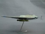
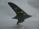
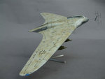

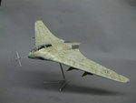
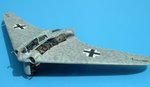
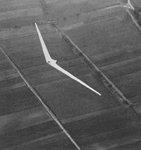
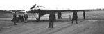
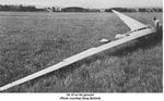
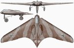
![Horten Ho VII[1]. 1.jpg](/forum/data/attachments/26/26054-b1526a15242b15c8219904505ab7feff.jpg)