Identification of aircraft part found former Luftwaffe Air Base in Denmark (1 Viewer)

7
3
Joined
Jul 1, 2026
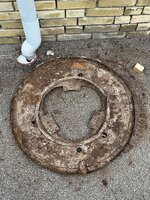
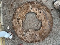
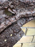
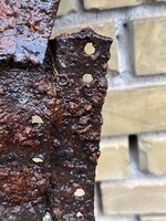
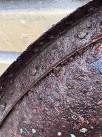
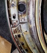
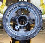
Can anyone help identify this aircraft part?

I found it buried at a former Luftwaffe Air Base in Denmark

* Diameter: just under 1 meter (approx. 39")
* Steel construction
* Originally riveted to an aluminium structure
* Features three equally spaced mounting brackets pointing toward the centre
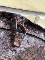
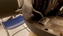
* Has an over-centre latch/clamp on the outer rim
* Appears to be part of a much larger assembly rather than a complete component

Due to the location and construction, I suspect it may be from a WWII military aircraft, but I have not been able to identify it.

Does anyone recognize it, or have any ideas what aircraft or system it could belong to?
 

Attachments

  • att.Qwyfrw3zto2xW8e6zzrkRz5SlGheXLvQ2INO1YdWIGg.jpeg
    att.Qwyfrw3zto2xW8e6zzrkRz5SlGheXLvQ2INO1YdWIGg.jpeg
    495.6 KB · Views: 37
  • att.jJnkTau_Hqr9uQo1r5EowXncnWgNN8aQPMgVwddbUh0.jpeg
    att.jJnkTau_Hqr9uQo1r5EowXncnWgNN8aQPMgVwddbUh0.jpeg
    513.5 KB · Views: 53
  • att.uqG3obqJV7DTkScDYRQReQ_49OmPBi0nk9Pmad3xDFA.jpeg
    att.uqG3obqJV7DTkScDYRQReQ_49OmPBi0nk9Pmad3xDFA.jpeg
    254.2 KB · Views: 37
  • att.aSg4nRWEsMla1eQZX1djkfZOQl2CfbQxrpt3biEltvE.jpeg
    att.aSg4nRWEsMla1eQZX1djkfZOQl2CfbQxrpt3biEltvE.jpeg
    284.7 KB · Views: 34
  • att.0Ktz6zWECRIvu1oxgKDHnw-dVtmR7lOgYahenCpB_w0.jpeg
    att.0Ktz6zWECRIvu1oxgKDHnw-dVtmR7lOgYahenCpB_w0.jpeg
    380.2 KB · Views: 44
  • att.sRhr7rvjRhiBtteUpB-xPj3VYx_NV5krJPay_T5N-sg.jpeg
    att.sRhr7rvjRhiBtteUpB-xPj3VYx_NV5krJPay_T5N-sg.jpeg
    226.9 KB · Views: 38
  • att.v-77KZM6tmwZZZ0n9Z37NwJ--aGolGJwUJvYYCiadho.jpeg
    att.v-77KZM6tmwZZZ0n9Z37NwJ--aGolGJwUJvYYCiadho.jpeg
    294.3 KB · Views: 41
It looks similar to a propeller rear spinner bulkheads
Michael beat me to it.
:thumbright:
Here are the details that give it away.
Note the 3 lobes, it was for a 3 bladed propeller.
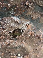
see that ring around there, with the little bit of tubing coming out for each blade? That is propeller anti-icing. I have a plane with the vestiges of that system on it.
it is called a slinger ring. A fixed tube drops the alcohol into that ring and centrifugal forces send it out the 3 little tubes.
 
Last edited:
Can anyone help identify this aircraft part?

I found it buried at a former Luftwaffe Air Base in Denmark

* Diameter: just under 1 meter (approx. 39")
* Steel construction
* Originally riveted to an aluminium structure
* Features three equally spaced mounting brackets pointing toward the centre
* Has an over-centre latch/clamp on the outer rim
* Appears to be part of a much larger assembly rather than a complete component

Due to the location and construction, I suspect it may be from a WWII military aircraft, but I have not been able to identify it.0

Does anyone recognize it, or have any ideas what aircraft or system it could belong to?
Hi,

This is a German WW2 VDM spinner backplate, most probably from one of the Luftwaffe aircraft left after the war. The 3 mounting brackets were a close tolerance fit onto the machined
faces on the rear of the Forged steel VDM prop hub and the size of that fitting radius or diameter would help id the particular application, as would the accurate outer diameter and the detail of the slinger ring for prop de-icing.
The latch is a simple spring loaded blocking plate mechanism that fitted a slot in the rotating ring of holes around the edge that engaged about 50 top-hat pins on the front spinner cover.
With the de-icing slinger fitted, this item was probably fitted to a larger aircraft, possibly even a He 219 nightfighter, but certainly a larger all-weather aircraft.
This backplate was fitted to the prop hub by machine screws on the 3 brackets. It has obviously been removed (dismantled) from the prop hub during scrapping and discarded due to its light construction and mixed metals, it had an alloy outer ring rivetted on.

Eng
 
Last edited:
Michael beat me to it.
:thumbright:
Here are the details that give it away.
Note the 3 lobes, it was for a 3 bladed propeller.
see that ring around there, with the little bit of tubing coming out for each blade? That is propeller anti-icing. I have a plane with the vestiges of that system on it.
it is called a slinger ring. A fixed tube drops the alcohol into that ring and centrifugal forces send it out the 3 little tubes.

Hi,

Your observation that this was for a 3 bladed propeller is correct. The defining feature here is really the 3 attachment brackets that were a close tolerance fit on the VDM prop hub, each bracket was fastened to a blade bearing housing on the hub, so 3 attachment brackets equals 3 blade housings, equals a 3 blade prop.

Cheers

Eng
 
I didn't have to see it beyond the slinger and the 3 feed tubes, that part is quite similar to the aluminum backplate for the Hartzell propeller with anti icing fitted to the early Cessna 310.
Many of the parts and switches in the old 310s are WW2 era.
 
I didn't have to see it beyond the slinger and the 3 feed tubes, that part is quite similar to the aluminum backplate for the Hartzell propeller with anti icing fitted to the early Cessna 310.
Many of the parts and switches in the old 310s are WW2 era.

Yes, the slinger ring with the 3 delivery tubes is a very good bit of evidence.
Here is an early illustration of the VDM hub, operating drive and spinner, see the date April 1939. This was the early type of VDM prop with a separate pitch change gearbox
pitch adjustment. Later, VDM pitch control units were generally integrated into the nosecase of the engine on DB and BMW engines after 1940.

Eng


109 (2) 003.jpg
 
Hi,

This is a German WW2 VDM spinner backplate, most probably from one of the Luftwaffe aircraft left after the war. The 3 mounting brackets were a close tolerance fit onto the machined
faces on the rear of the Forged steel VDM prop hub and the size of that fitting radius or diameter would help id the particular application, as would the accurate outer diameter and the detail of the slinger ring for prop de-icing.
The latch is a simple spring loaded blocking plate mechanism that fitted a slot in the rotating ring of holes around the edge that engaged about 50 top-hat pins on the front spinner cover.
With the de-icing slinger fitted, this item was probably fitted to a larger aircraft, possibly even a He 219 nightfighter, but certainly a larger all-weather aircraft.
This backplate was fitted to the prop hub by machine screws on the 3 brackets. It has obviously been removed (dismantled) from the prop hub during scrapping and discarded due to its light construction and mixed metals, it had an alloy outer ring rivetted on.

Eng

Thanks a lot for the answer!
 
Hi,

This is a German WW2 VDM spinner backplate, most probably from one of the Luftwaffe aircraft left after the war. The 3 mounting brackets were a close tolerance fit onto the machined
faces on the rear of the Forged steel VDM prop hub and the size of that fitting radius or diameter would help id the particular application, as would the accurate outer diameter and the detail of the slinger ring for prop de-icing.
The latch is a simple spring loaded blocking plate mechanism that fitted a slot in the rotating ring of holes around the edge that engaged about 50 top-hat pins on the front spinner cover.
With the de-icing slinger fitted, this item was probably fitted to a larger aircraft, possibly even a He 219 nightfighter, but certainly a larger all-weather aircraft.
This backplate was fitted to the prop hub by machine screws on the 3 brackets. It has obviously been removed (dismantled) from the prop hub during scrapping and discarded due to its light construction and mixed metals, it had an alloy outer ring rivetted on.

Eng

Hi,

it's 76 cm in diameter
 
Hi,

it's 76 cm in diameter
Unfortunately the VDM parts documents don't give the size details, that is all in the production drawings that I do not have. There are thousands of them, somewhere.
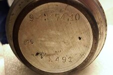
However, the closest match I can find with the slinger ring and tube feeds is part nr 9-11 177.34 which is listed for the Ju 88 with JUMO 211 engines. This is not
a positive id but, it is likely.

Eng
 
I was fortunate to help assemble the props for the NASM He219. Here are a few images when we did that. Note the backplate view is from the engine side. The close-up of the de-icing tube to the blade, and the latching plate for the spinner. You can witness the holes where the spinner tabs slide into the plate.

Tony
 

Attachments

  • He219_Prop_Spinner_Latch.jpg
    He219_Prop_Spinner_Latch.jpg
    152.4 KB · Views: 48
  • He219_VDM_Prop_Backplate_facing_engine.jpg
    He219_VDM_Prop_Backplate_facing_engine.jpg
    1.5 MB · Views: 41
  • He219_VDM_Prop_Slinger.jpg
    He219_VDM_Prop_Slinger.jpg
    47.3 KB · Views: 37
I was fortunate to help assemble the props for the NASM He219. Here are a few images when we did that. Note the backplate view is from the engine side. The close-up of the de-icing tube to the blade, and the latching plate for the spinner. You can witness the holes where the spinner tabs slide into the plate.

Tony
Very nice Tony!
You can see those late War hubs are roughly machined as well! I have a couple of pics from the VDM parts list at the end, it is dated Mar '44 and does not cover all the very late details.
It does have 3 listings for the He 219 which I show. The first line 60, 9-12132 B is actually a 4-bladed prop, so not yours.
The next 2 lines ( 61 and 62) show two very similar propeller units, the 9-12174A and the B. If you read carefully, you can see that they differ slightly with just the last digit difference in the blade part number and the spinner part number, although they are shown interchangeable in the notes. It will mean there is some slight difference but you can't tell!
Unfortunately, these parts are not illustrated, the illustrations generally disappear from most German technical publications during 1944.
There is an illustration of a similar spinner backplate to your photos with the particular style of de-icing feed lines in your pics. This is the second pic and it is an earlier prop,
the 9-12068.31 . This is just to illustrate the difference in the de-icing feeds from those of the relic in this thread which fed into a transfer pipe running forward, so I don't think the relic part is for a He 219.

Cheers

Eng


vdmhe219g.jpg


vdm1206831f.jpg
 
were these variable pitch or constant speed propellers at that time?
Did they feature full feathering?
 
were these variable pitch or constant speed propellers at that time?
Did they feature full feathering?

The VDM system was both! They started in the mid 30's by being a variable pitch prop, the first versions as on the Me 108 and other small engines had a small manual winding handle in the cockpit that turned a flexi shaft connected to the VDM gear train system around the propeller shaft and transmitted the differential movement to the prop pitch adjustment gears.
This was developed to operate with a small electric motor and switch. Enlarging everything, this was then produced for large aircraft and engines. The pilot could use the 3-way switch to drive the prop coarser or finer or hold, the actual blade pitch being read on a clock-face type instrument. The design of the pitch change drive with spur gears, shafts and worm gears onto the blade roots made the range of movement as large as required although most set-ups were given electric limit switches acting as fine and coarse stops.
In early versions of Bf 109, the pitch switch was on the instrument panel but this was not a very good arrangement and by 1940 a throttle mounted rocker thumbswitch had been devised. The next development was to add a variable datum centrifugal governor on the engine. This governor had the variable datum linked to throttle position so that the engine ran at increasing rpm with increased throttle. A manual/auto changeover switch allowed the pilot to adjust prop pitch manually if required, eg for feathering. The feathering coarse pitch stop was at the aerodynamic minimum drag pitch angle for twins and multi engine types. For single engine aircraft the coarse pitch stop was around 70 degrees blade pitch.
The Throttle position / rpm linked control was also used on some late Spitfires, although Allied aircraft usually had an rpm lever to set rpm.

Eng
 
Thanks. I flew the Woodward governed hydraulically actuated propellers common to the 50's and 60's. no variable control, only a governor interaction and you found out what the low speed/course setting was, and it was just above a detent that took it to feather.
In the early 310 it would dial down to 1950 RPM.
 
Thanks. I flew the Woodward governed hydraulically actuated propellers common to the 50's and 60's. no variable control, only a governor interaction and you found out what the low speed/course setting was, and it was just above a detent that took it to feather.
In the early 310 it would dial down to 1950 RPM.

The VDM system on the WW2 Big DB engines generally controlled between 1900 and 2800 rpm, matching the ratings of the engines by a profiled cam that altered the control effect
of the throttle position movement to match. In manual control, it was possible to achieve different manifold pressure/rpm relationships, although this was not really recommended, except for special low rpm/wide throttle operation on special LRC ops.
It is not a bad system but, it takes some lateral thinking if you are used to an Allied aircraft with an rpm lever and the much more liberal RPM/Manifold pressure relationships on, for example, the Merlin.
Cheers

Eng
 
In the opposed naturally aspirated engines, you tended to square operations EG 23" MP/2300RPM for cruise.
There are certain engine/propeller combinations with prohibited arcs due to vibration characteristics. You can pass through but do not hang out in those arcs.
I achieved best range and economy in a power setting that was off the performance charts on the low side, @20"/2100RPM or so.
Best range on 1 would probably be similar or whatever can keep best L/D at the selected altitude.
In multi engine aircraft, all those numbers come together to hint at the best L/D point on the curve.
Using the 310 numbers as an example:
Best glide 109
VYSE ( best single engine rate of climb) 111
VY ( best rate of climb all turning) 119
Those are all based on a clean wing and MTOW.
It would be a long slog at ~110 MPH but that would net best range, and while not intuitive nor safe-sounding, shutting down 1 will get you farther over the open ocean than running both or all of them.
Oil consumption comes into play. The modified plane with extended tanks had a plug in the oil pan to increase capacity for long flights, and that was based on acceptable oil consumption from the engine manufacturer.
 
In the opposed naturally aspirated engines, you tended to square operations EG 23" MP/2300RPM for cruise.
There are certain engine/propeller combinations with prohibited arcs due to vibration characteristics. You can pass through but do not hang out in those arcs.
I achieved best range and economy in a power setting that was off the performance charts on the low side, @20"/2100RPM or so.
Best range on 1 would probably be similar or whatever can keep best L/D at the selected altitude.
In multi engine aircraft, all those numbers come together to hint at the best L/D point on the curve.
Using the 310 numbers as an example:
Best glide 109
VYSE ( best single engine rate of climb) 111
VY ( best rate of climb all turning) 119
Those are all based on a clean wing and MTOW.
It would be a long slog at ~110 MPH but that would net best range, and while not intuitive nor safe-sounding, shutting down 1 will get you farther over the open ocean than running both or all of them.
Oil consumption comes into play. The modified plane with extended tanks had a plug in the oil pan to increase capacity for long flights, and that was based on acceptable oil consumption from the engine manufacturer.
Here is the base of one of the prop blades from the He219.
 

Attachments

  • He219_Prop_Blade_Base.jpg
    He219_Prop_Blade_Base.jpg
    84.6 KB · Views: 39

Users who are viewing this thread

Back