Scratch build Boeing F4B-4

Ad: This forum contains affiliate links to products on Amazon and eBay. More information in Terms and rules

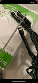
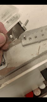
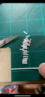
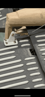
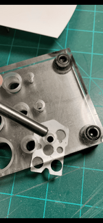
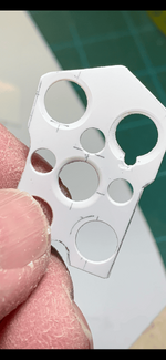
I used a small file to round out the top. I was lucky that the lights were made from plastic & not glass.

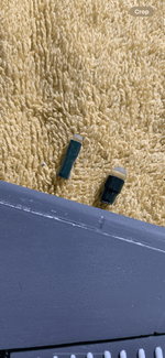
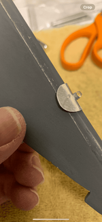
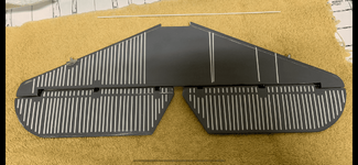
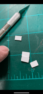
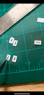
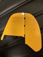
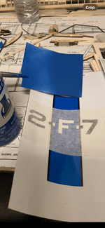
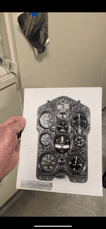
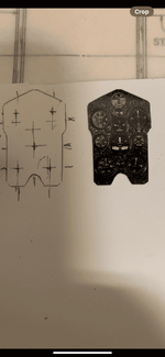
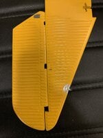
I then compared which would be the ideal size. I chose the smaller one as it appeared to be in correct proportion.
 

Attachments

  • IMG_9026.png
    IMG_9026.png
    399.2 KB · Views: 2
  • IMG_9027.png
    IMG_9027.png
    370.3 KB · Views: 1
  • IMG_9028.png
    IMG_9028.png
    645.9 KB · Views: 2
Following Westburg's drawings (& other photos) I used a thick aluminum foil similar to chrome plumber's duct tape to fabricate the aluminum mounts.

I used a modeler's punch & die set (obtainable from MicroMark) to punch out the hole. I found from past experience it's far easier to punch the hole first, then cut out the surrounding mount later.
 

Attachments

  • IMG_9023.png
    IMG_9023.png
    303.5 KB · Views: 2
  • IMG_9021.png
    IMG_9021.png
    363.4 KB · Views: 2
  • IMG_9020.png
    IMG_9020.png
    331.3 KB · Views: 2
The tedious cutting, filing & sanding of each strip commenced. The short strips used on the leading edges of the elevators were the few exceptions of cutting separate strips & I could "gang cut" several at a time.

More wine, please… 😁
 

Attachments

  • IMG_9018.png
    IMG_9018.png
    561.2 KB · Views: 1
  • IMG_9031.png
    IMG_9031.png
    301.4 KB · Views: 2
  • IMG_9030.png
    IMG_9030.png
    303.5 KB · Views: 1
  • IMG_9032.png
    IMG_9032.png
    499.6 KB · Views: 2
  • IMG_9023.png
    IMG_9023.png
    303.5 KB · Views: 1
This is most intriguing, just trying to keep up with you is mind boggling and I do not envy your doing the corrugation but that was a good solution with sealing the balsa for it is such a soft wood, you'll never get it to a smooth surface. You are doing well. :thumbright: :lol:
 
Hinges were fabricated out of thin plastic sheets. The sheets were thick enough to give the base support that " beefy look" yet still be thin enough to avoid looking like a toy.

The corners were rounded off.

Two holes on opposite sides were drilled using a pin vise. All I needed to do was "connect the dots" by using a # 11 X-Acto blade & cutting a line on either side of the holes to get a nice slot with rounded ends.

This certainly solved the problem of cutting out the ends.

The tricky part came when I was making the control horns. I cut tiny pieces of brass tubing to fit inside the holes to act as bushings for the stranded wire (thread).

I had to match up the drill bit with the outside diameter of the brass tubing & still make sure the whole assembly fits within the control horn.
 

Attachments

  • IMG_9053.png
    IMG_9053.png
    261.2 KB · Views: 2
  • IMG_9005.png
    IMG_9005.png
    398.4 KB · Views: 1
  • IMG_9006.png
    IMG_9006.png
    427.7 KB · Views: 1
  • IMG_9004.png
    IMG_9004.png
    488.7 KB · Views: 1
  • IMG_9003.png
    IMG_9003.png
    345.8 KB · Views: 1
I posed the sub assemblies of the horizontal & vertical stabs as they are currently at this stage.

I used several coats of rattle can Testor's enamel paint to get a hard & durable finish.

Each coat was lightly sprayed to slowly build up the desired color. If I were to attempt to apply it in one heavy coat, I risk the chance of running paint.

I also had to spray from different angles to cover areas that were "shaded" by the corrugated strips.
This is most intriguing, just trying to keep up with you is mind boggling and I do not envy your doing the corrugation but that was a good solution with sealing the balsa for it is such a soft wood, you'll never get it to a smooth surface. You are doing well.
 

Attachments

  • image.jpg
    image.jpg
    1.5 MB · Views: 1
  • image.jpg
    image.jpg
    2 MB · Views: 1
  • image.jpg
    image.jpg
    1.7 MB · Views: 1
Good afternoon everyone. I'm in the process of collating the detailed photos of the interior of both the model & full sized aircraft. As of this writing, there are approximately 130 photos alone. So I'll need just a bit more time to organize the presentation.

Thank you for your patience.
 
Good evening everyone:

I thought before commencing on the postings of the cockpit interior, you might like to see my end goal. Thus, the 5-view presentation is from the book: Aircraft in Profiles # 27 from Vol. 2 of the series.

I have already received the custom graphics from a gentleman named Geoff Gill of U.K. & has done outstanding work right down to matching the blue tone on my Rustoleum rattle can.

There are several other accessories that were ordered & received from various sources & I'll be posting them as well. If anyone is interested in contacting Mr. Gill or any of the vendors, please let me know.

To our more astute observers, the number 7 is actually a separate graphic on the same sheet & will be properly oriented within the blue chevron upon applying over the top wing.

Just as on the P-51 Mustang, there are conflicting information & I try to use the most valid source, this is usually in the form of photographs & I'll point these out as I go along.

I'll also point out the differences between the P-12E & the F4B-4.

As always, please feel free to chime in & offer suggestions / observations / comments.

Cheers,

Gary
 

Attachments

  • IMG_9178.png
    IMG_9178.png
    448.2 KB · Views: 1
  • IMG_9220.png
    IMG_9220.png
    415.8 KB · Views: 1
  • IMG_9221.png
    IMG_9221.png
    378.1 KB · Views: 1
Last edited:
I used as much of the commercially available sources on the Internet, Mr. Peter Westburg's drawings (he did outstanding inboard profiles showing the placement of various accessories within the interior), my own b+w photos taken of the Boeing P-12E on display at the Planes of Fame air museum in Chino, California & from the Nat'l Museum of Naval Aviation in Pensacola, Florida.

I'll post a few of the pictures now.
 

Attachments

  • IMG_9213.png
    IMG_9213.png
    421.2 KB · Views: 0
  • IMG_9192.png
    IMG_9192.png
    408.8 KB · Views: 0
  • IMG_9129.png
    IMG_9129.png
    288.5 KB · Views: 0
  • IMG_9103.png
    IMG_9103.png
    380.6 KB · Views: 0
Oddly enough, the main instrument panel was one of the easiest accessory to make & it was one of the first few I fabricated right at the beginning.

My source was from Westburg's personal collection -he sold it to me tars ago.
 

Attachments

  • IMG_9211.png
    IMG_9211.png
    369.3 KB · Views: 0
To make this panel, I sized up the overall dimensions by the tried & true eyeball method using the "lt looks about right" & combined with the proportion to the surrounding areas.

A modeler's punch & die was used to punch out the holes for the instruments. This is available through MicroMark & well worth the investment.

Next, I used a punch that was slightly larger than the hole made from the previous punch & using the bevel end instead of the sharp punch to make holes, I gently tapped it with my hammer to get that "in-depth" recessed look.

This was followed up by using a rattle can & spraying flat black at a greater distance than normal to get that " splatter" effect.

Finally, I took the photo of the actual instrument panel, taped it to my garage door entrance to my home & tried various distances to get the size of the panel reasonably close to scale.
 

Attachments

  • IMG_9208.png
    IMG_9208.png
    221 KB · Views: 1
  • IMG_9207.png
    IMG_9207.png
    517.8 KB · Views: 1
  • IMG_9201.png
    IMG_9201.png
    361.1 KB · Views: 1
  • IMG_9206.png
    IMG_9206.png
    591.7 KB · Views: 0
  • IMG_9212.png
    IMG_9212.png
    240.9 KB · Views: 0
The "front office" is utilitarian with breeches for a .50 caliber machine on the right & a .30. caliber in the left. Why Boeing chose this option? I have no idea.

Notice that there's no "wall" or former behind the instrument panel & there's space for the machine guns in either side of the instrument panel.
 

Attachments

  • IMG_9213.png
    IMG_9213.png
    421.2 KB · Views: 0

Users who are viewing this thread

Back