Scratch build Boeing F4B-4 (2 Viewers)

Ad: This forum contains affiliate links to products on Amazon and eBay. More information in Terms and rules

Skyediamonds

Staff Sergeant
1,266
716
May 26, 2018
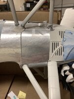
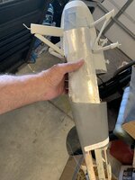
Good afternoon everyone. I'm in the middle of scratching out a wooden 1/10th scale 36" top wingspan Boeing F4B-4. It's for display & will ultimately be given to my son.

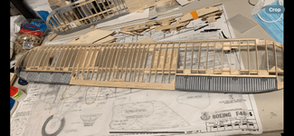
Both wings are framed up & waiting to be covered. The corrugated tail feathers & ailerons are finished & waiting to be installed.

All that remains is the fuselage & it's associated cabane & landing gear struts & of course all of the accessories & attachments.

I'll start this modeling post with a couple of photos of the fuselage as it stands as of July 9, 2024.
 

Attachments

  • IMG_8926.jpeg
    IMG_8926.jpeg
    1 MB · Views: 33
  • IMG_8975.jpeg
    IMG_8975.jpeg
    1.3 MB · Views: 28
Wurger, Vic & fellow members:

Thank you! I'll get started this morning. I'll start with my approach to the fuselage in general & cockpit interior in particular.

From there, I'll bounce off into how I tackled the corrugated surfaces (mind-blowing tedious job, but well worth the results) with a glance at the wings.

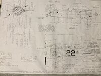
I'll also share what I was able to find on the full sized Boeing F4B-4 & P-12E along with their differences.
 
Thank you one & all! It's greatly appreciated.

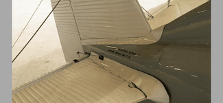
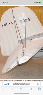
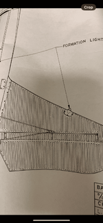
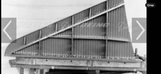
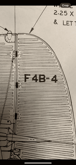
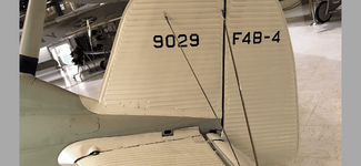
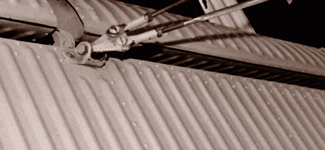
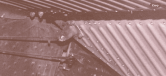
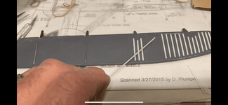
In honor of Special Ed, I'm starting on my approach to corrugating the flying surfaces. The reason why I thought it best to touch on this subject first is because it's one of those perplexing subjects in which everyone including myself would say; "How the heck does he do this?"

To begin:
As in almost all serious scale modeling, especially from scratch, a lot of research is involved; even if it focuses on just one small portion of the aircraft.

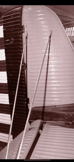
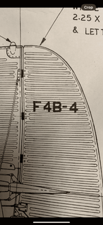
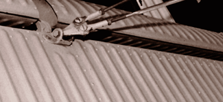
Here, I observed that the corrugations were unique to the Boeing biplane. Not too thin or too tight, but spaced out evenly almost to where each corrugated surface stood out on its own.

This was going to be a challenge…..
 

Attachments

  • IMG_9015.png
    IMG_9015.png
    327.9 KB · Views: 26
  • IMG_9013.png
    IMG_9013.png
    391.8 KB · Views: 22
  • IMG_9023.png
    IMG_9023.png
    303.5 KB · Views: 25
  • IMG_9017.png
    IMG_9017.png
    235.8 KB · Views: 27
  • IMG_9046.png
    IMG_9046.png
    332.4 KB · Views: 27
  • IMG_9047.png
    IMG_9047.png
    464.8 KB · Views: 26
  • IMG_9051.png
    IMG_9051.png
    281 KB · Views: 25
  • IMG_9053.png
    IMG_9053.png
    261.2 KB · Views: 27
  • IMG_9054.png
    IMG_9054.png
    297.2 KB · Views: 25
  • IMG_9057.jpeg
    IMG_9057.jpeg
    1 MB · Views: 28
I don't have 3-D printers. Nor did I wish to set up a complex mold for each vacuform surface.

I had a couple of choices. I wanted something solid & it would last a long time.

I looked into Evergreen plastic corrugated sheets. It turned out they were not of the type to fit the image of the "Boeing" corrugated surface.

It was at this point I knew that I had work cut out for me.
 

Attachments

  • IMG_9007.jpeg
    IMG_9007.jpeg
    820.5 KB · Views: 22
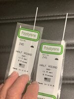
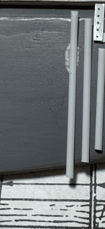
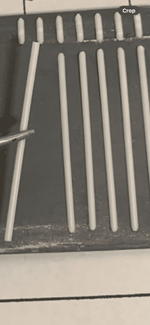
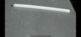
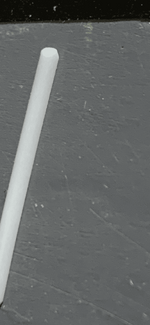
I decided to use half-round plastic strips & space them apart such that each would stand on its own. The key here, was the spacing.

I used .06" sized plastic half-round strips. They appeared to be " just about right."

Just for your info: Evergreen also makes, 1/4 round, 3/4 round & of course solid or complete round plastic strips of different sizes.
 

Attachments

  • IMG_9008.jpeg
    IMG_9008.jpeg
    1.2 MB · Views: 19
  • IMG_9046.png
    IMG_9046.png
    332.4 KB · Views: 18
As if just gluing dozens (& dozens) of strips were not enough, each end was going to have to be shaped & smoothed out.
 

Attachments

  • IMG_9023.png
    IMG_9023.png
    303.5 KB · Views: 21
  • IMG_9043.png
    IMG_9043.png
    631.3 KB · Views: 19
  • IMG_9049.png
    IMG_9049.png
    363.8 KB · Views: 19
Last edited:
They would also have to be cut out separately to account for the hinges & the curves along the trailing edges.
 

Attachments

  • IMG_9051.png
    IMG_9051.png
    281 KB · Views: 19
  • IMG_9056.png
    IMG_9056.png
    245.7 KB · Views: 22
  • IMG_9045.png
    IMG_9045.png
    277.2 KB · Views: 19
  • IMG_9048.png
    IMG_9048.png
    282.6 KB · Views: 20
  • IMG_9044.png
    IMG_9044.png
    296.5 KB · Views: 17
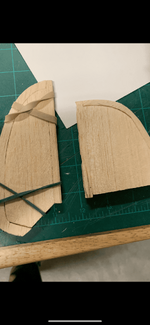
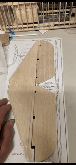
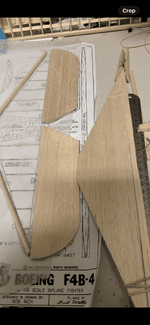
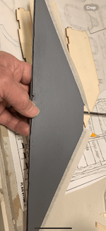
The tail feathers were fabricated from balsa frames & covered with balsa sheets. In hindsight I could've covered over the frames with sheets of plastic as the next steps will show….
 

Attachments

  • IMG_9012.png
    IMG_9012.png
    315.1 KB · Views: 21
  • IMG_9011.png
    IMG_9011.png
    361.1 KB · Views: 16
  • IMG_9034.png
    IMG_9034.png
    496.2 KB · Views: 16
  • IMG_9042.png
    IMG_9042.png
    438.4 KB · Views: 15
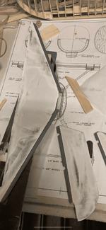
Silly me, I was only following instructions to use balsa sheets. No matter how smooth I sanded & primed the surfaces, the wood grain showed through. This was not acceptable.
 

Attachments

  • IMG_9037.png
    IMG_9037.png
    414.6 KB · Views: 15
  • IMG_9036.png
    IMG_9036.png
    380.8 KB · Views: 15
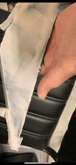
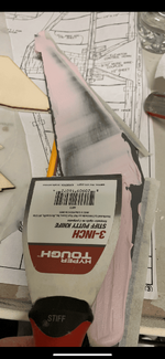
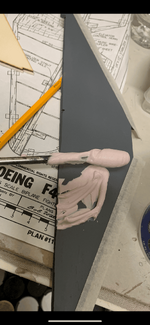
So, out comes the filler. In this case I used Spackling compound. It's a dry wall filler.

I had to apply this at least twice to get the desired smooth surface.
 

Attachments

  • IMG_9041.png
    IMG_9041.png
    413.9 KB · Views: 15
  • IMG_9040.png
    IMG_9040.png
    397.5 KB · Views: 14
  • IMG_9039.png
    IMG_9039.png
    458.6 KB · Views: 16
  • IMG_9038.png
    IMG_9038.png
    385.3 KB · Views: 15
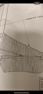
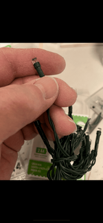
In between filler coats (& watching the filler dry) I turned my attention to formation lights. I knew these tiny Christmas lights would come in handy. It was just a matter of picking out the right size, using the tried & true eyeball method.
 

Attachments

  • IMG_9023.png
    IMG_9023.png
    303.5 KB · Views: 15
  • IMG_9024.png
    IMG_9024.png
    274.4 KB · Views: 13

Users who are viewing this thread

Back