Tare Weight Data, Lancaster X KB.721

Ad: This forum contains affiliate links to products on Amazon and eBay. More information in Terms and rules

JDCAVE

Senior Airman
575
971
Aug 17, 2007
I got a chuckle out of this! Dad did 7 ops on this aircraft.

Lancaster X KB.721 Weight data (wwiiaircraftperformance.org)

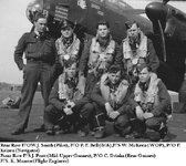
And here she is, photo by F/Lt HHM Cave.


B Baker KB 721 by Cave at Middleton.jpg


Later the Nose-art changed. Brick Bradford was removed and a Rose painted on it instead. Here is a colour photo taken just before she was scrapped, Aylmer Ontario.
After dad flew her, she was flown by F/O J.W. Smith, who flew her back to Canada. He took the colour photo.

Jim

KB 721 Colour.jpg
 
Last edited:
Quite possible the front turret was removed when it was scrapped....419 Squadron RCAF 1941 to 1945 Lancaster KB721
Linden Rose KB721

Probably.

Ahhh! Lancaster Archive! To say I'm not a fan of this individual would be putting it mildly! He shut down the Lancaster Archive Forum and refused access to all who posted on it. Several veterans posted on this forum. "Dennis" a 5-Group tail gunner had over 2000 posts, which served as his wartime memoirs. He was denied access to his posts. He was his wife's caregiver, and the Forum was a big part of his social contact with people. The photos the proprietor has of KB.721 came from forum members, including the first black and white one, above which was taken by my father. People posted hundreds of photos and other information on the forum and only he has access to it. So, in my view what he did was reprehensible, amongst other things, including possible copyright issues.

Jim
 
Last edited:
Probably.

Ahhh! Lancaster Archive! To say I'm not a fan of this individual would be putting it mildly! He shut down the Lancaster Archive Forum and refused access to all who posted on it. Several veterans posted on this forum. "Dennis" a 5-Group tail gunner had over 2000 posts, which served as his wartime memoirs. He was denied access to his posts. He was his wife's caregiver, and the Forum was a big part of his social contact with people. The photos the proprietor has of KB.721 came from forum members, including the first black and white one, above which was taken by my father. People posted hundreds of photos and other information on the forum and only he has access to it. So, in my view what he did was reprehensible, amongst other things, including possible copyright issues.

Jim
Thanks. Sorry to have stirred the nest...
 
The actual weight data is in part 2 due to the 20,000 character limit. Weights in pounds. Firstly the usually quoted official weights and performance figures for the Avro Lancaster, from the book by Harry Holmes.

Production Lancaster I. Range 2,530 miles with 7,000 pound bomb \load, 1,730 miles with 12,000 pounds, 1,550 miles with 22,000 pounds Tankage 2,154 gallons.

Maximum speeds 287 mph at 11,500 feet, 275 mph at 15,000 feet, 260 mph at 19,400 feet. Cruising speeds 234 mph at 21,000 feet, 200 mph at 15,000 feet. Service ceiling 23,000 feet, absolute ceiling 24,500 feet. Weights in pounds. The / are of course column markers.

Jan-42 / Sep-42 / Nov-42 / May-44 / Early 1945 / Month
I / II / I / I & III / I & III Overload / Mark
17,064 / 17,064 / 17,776 / 18,033 / 17,633 / Structure
10,720 / 12,335 / 11,304 / 11,610 / 11,610 / Power plants
1,796 / 1,796 / 1,990 / 1,999 / 1,999 / Fuel and oil tanks
29,580 / 31,195 / 31,070 / 31,642 / 31,242 / Empty weight
4,120 / 4,120 / 4,334 / 5,169 / 4,589 / Fixed military load
33,700 / 35,315 / 35,404 / 36,811 / 35,831 / Tare weight
26,300 / 24,685 / 27,596 / 28,189 / 36,169 / load
60,000 / 60,000 / 63,000 / 65,000 / 72,000 / Gross Weight
5,120 / 6,200 / 5,120 / 6,440 / 6,440 / take off power bhp
46.26 / 46.26 / 48.57 / 50.12 / 55.51 / Wing load lb/sq ft
5.77 / 5.77 / 6.06 / 6.25 / 6.92 / Span load lb/sq ft
11.72 / 9.68 / 12.30 / 10.09 / 11.18 / Power load lb/bhp

A document from the Australian Archives, unfortunately undated, it reads as a form of wartime sales brochure, and is connected to the local desire to have a Lancaster production line in Australia, which became the post war Lincoln production line. Hence the twin wasp engine option, given Australia was manufacturing the engine. The photograph in the file is of Lincoln RE228.

The weights quoted are clearly from the earlier Lancaster production and/or the prototypes. To give some sort of idea of a possible date of writing consider,

Centaurus engine production started in October 1942, Sabre in Q4/1940
Lancaster 1st prototype BT308 first flight 9 January 1941
Lancaster 2nd prototype DG595 first flight 13 May 1941.
Lancaster II prototype DT810 first flight 26 November 1941
Lancaster I production began in October 1941
Lancaster II production began in August 1942.

The idea the Sabre could be fitted to a number of aircraft was current until mid war, probably 1942. The Vulture maybe 1941.

Anyway from now on comes the document. Most of the numbers are at the end. Including a very detailed break down of fixed and removable military load.

Avro Lancaster

General Description. The Avro Lancaster is a four-engined mid-wing monoplane of all metal construction, designed to operate as a heavy bomber. The aircraft may also be used as a long range general reconnaissance type. The overall dimensions area: Span 102 feet, length 70 feet, height 19 feet 6 inches, wing area 1,300 square feet. The maximum loaded weight is 60,000 pounds. A crew of six is usually carried. Fuel tankage for a still air range of 3,000 miles, at an economical cruising speed of 200/215 m.p.h. is provided. All the fuel tanks are in the wing and they are of the self sealing type. Jettison valves are fitted to jettison 1,000 gallons. For reinforcing flights where very long distances have to be covered, additional fuel tanks can be mounted inside the bomb compartment. The official test figures for the prototype Lancaster gave a cruising speed of 285 m.p.h. at the continuous cruising power of the Merlin XX engines using weak mixture, but at this cruising speed the range with standard tankage is reduced, as shown in the accompanying charts. Bomb loads of up to 12,750 pounds can be carried. All the bomb load is carried in one large compartment which forms the lower portion of the fuselage and which is closed by means of two long doors which conform to the streamline shape of the fuselage and are hydraulically operated. This arrangement of bomb compartment enables all the standard sizes of bomb to be accommodated, including the latest very large bombs. The bomb carriers and bomb housings are of the Avro type, which has been standardised for use in the R.A.F. An effective bomb sighting position is provided in the extreme nose of the fuselage.

An important feature of the design is that a large variety of different types of power plant can be installed. This is made possible by the use of easily detachable sub-mounting frames. The Lancaster can be supplied either as a twin engined aeroplane or a four engined aeroplane, using engines of 2,000 h.p. or 1,000 h.p. For example power unit installations are already designed, or are in the process of design to accommodate the following engines:- Four engined, Rolls Royce Merlin XX or Pratt and Whitney Twin Wasp or Bristol Hercules. Twin engined, Rolls Royce Vulture, Bristol Centaurus, Napier Sabre. The Lancaster is at present in production using the Rolls Royce Merlin XX engines. The airscrews are of the fully feathering, constant speed type.

Design developments are in hand to adapt the aircraft for ultra high altitude operation.

The Lancaster is provided with a very effective defence, consisting of three power operated gun turrets. These comprise, a twin gun nose turret, a four gun tail turret and a twin gun mid-upper turret. All the guns can be brought to bear on the beam converging at a distance of about 100 yards from the aircraft, and the mid upper turret provides effective reinforcing fire for both the rear and forward turrets. This strong defensive armament, coupled with the very high speed of the aircraft, makes the Lancaster a very difficult machine to attack by fighters.

The Lancaster is remarkably controllable for its size, which enables it to take effective evasive action when attacked and also during bombing operations.

Excellent armouring is provided. This consists of an armour plate bulkhead in the form of two large doors, which completely bulkhead off the forward crew compartment. The pilot's seat is provided with separate armour and the fire control station alongside the pilot is fitted with a bullet proof glass shield to protect the fire control officer's head and shoulders.

The construction of the Lancaster airframe is simple. A great deal of care was taken during the design stage to simplify both the main components and the details; this simplicity of construction has been well proved in actual manufacture. The materials mainly used throughout the airframe are aluminium alloy and steel, aluminium alloy forming the major portion of the constructional material. Hydraulic power is provided for the operation of undercarriage, landing flaps, bomb doors, gun turrets, airscrews, etc. Electrical power is provided for engine starting, radio, intercommunication telephones, lighting, instrument operation, bomb fusing and firing, etc.

Cabin heating is provided and this has been tested to high altitudes and low temperatures with very satisfactory results. The cabin heating is controllable and can be varied to suit the temperature at which the aircraft is operating. The pilot and fire control officer are accommodated in a roomy cabin which has a completely transparent top raised above the general top of the fuselage and carefully streamlined. This raised canopy gives them an exceptionally good all round field of view, which is considered to be a valuable military asset, particularly when the aircraft is subjected to air attack. The pilot's windscreen is provided with a clear vision panel which can be opened without any draught entering, and in addition the main windscreen is fitted with windscreen wipers. The pilot's seat and rudder pedals are bit adjustable for height and distance, so that pilots of different heights can be comfortably seated. Single control is provided for the pilot, but dual controls can be installed for instructional purposes. An automatic pilot is fitted to relieve the pilot of flying strain during the long flights, or under conditions of blind flying. Blind landing apparatus is installed.

The large dimensions of the fuselage enable all the standard military equipment to be accommodated and the Lancaster is particularly well equipped in this respect. For reinforcing flights, additional seats can be fitted in the fuselage to seat twelve squadron personnel. Side light and roof lights are fitted along the fuselage so that the interior is sufficiently light to enable work to be carried on during the day time without artificial lighting. Curtains are fitted for night operations.

Emergency parachute exits are fitted in the bottom of the fuselage and emergency exits on the top of the fuselage for use in the case of a forced landing with the undercarriage up and where the main door maybe jammed.

Construction.

Fuselage. The fuselage is a straight forward light alloy monocoque, built up on a framework of hoops and stringers with flush rivetted skin. To facilitate manufacture and transport, the fuselage is divided into five sections which are fastened together by rings of bolts at the transport joints. This sub division of the fuselage has proved of great value, as it enables a large number of work people to operate at the same time without interfering with one another. Where strong points are necessary, use is made of high grade aluminium alloy forgings and castings. The hoops or formers are developed from sheet in presses. The stringers may be either of extruded aluminium alloy sections or drawn sections made from strip. Alternatives are provided in the drawings.

Wing. The wing is of the two spar type with pressed ribs and flush riveted covering. Like the fuselage, the wing is constructed in a number of sections which are bolted together. This is done to facilitate construction and transport. Compartments are fitted in the wing to contain the fuel tanks, the undercarriage and the emergency dinghy. The leading edge of the wing is fitted with B.B.P. gear. Frise type ailerons are employed and these are mounted on self aligning ball bearings. The trailing edge flaps are of the conventional split trailing edge type. The centre section leading edge is arranged to fold upwards easily to give access to the engine controls, electrical cables, hydraulic piping, etc. Inspection doors are fitted wherever necessary to give easy access to interior piping, wiring, etc.

Tailplane. The construction of the tailplane is on the same lines as that of the main plane. The elevator is a welded tubular structure with fabric covering and is both mass balanced and aerodynamically balanced. Trimming tabs are fitted for operation by the pilot.

Fins and Rudders. The twin fins and rudders are both metal covered structures and the rudders are fitted with trimming tabs to relieve the load on the pilot's foot when flying with one or two engines stopped on one side. The trimmers are sufficiently powerful to enable this to be done without any load on the pilot's foot.

Undercarriage. The undercarriage is of a very simple design for so large an aeroplane. Two independent units are used, one under each of the inboard engine supporting points. The undercarriages are hydraulically operated and retract backwards onto a fairing which is a continuation of the inboard engine nacelles. When retracted, the undercarriages are completely enclosed by means of doors which are coupled to the undercarriage themselves and thus automatically open and shut when the undercarriages are lowered and raised. A long travel is provided on the shock absorber struts, which are of the air-cum-oil type, the air acting as the taxying spring and the oil providing the hydraulic energy absorption. Efficient wheel brakes are incorporated, which are operated by compressed air from a control on the pilot's wheel.

Tail wheel. The tail wheel is not retractable. The shock absorber is of the air-cum-oil type. The tail wheel can rotate through 360 degrees for manoeuvering on the ground and the whole unit can be removed from the aircraft by the removal of one large bolt.

Flying controls.
The flying controls are of the column and wheel and foot pedal type; either single control or dual control can be fitted. The dual control consists of attachments to the single control. The rudder pedals are quickly adjustable to suit pilots of different heights. The forces from the control column and foot pedals are transmitted through the aircraft by means of push-pull control rods. All control services are mounted on ball bearing hinges of the self aligning type. A folding seat alongside the first pilot's seat provides a side by side pilots' station.

Engine controls. Particular care has been taken in the design of the engine controls to provide easy and exact operation of the carburettor, mixture, airscrews, etc. The system is mechanical and consists of levers connected by means of chains and sprockets and tie rods. The engine control system is given a small degree of pretension which eliminates all backlash. The engine controls are mounted throughout on ball bearings. This system of engine controls, whilst somewhat elaborate, is remarkably free of friction and enables the rather heavy loads which have to be dealt with in large sized engines to be easily overcome by the pilot. Freedom from backlash gives the accuracy of the control necessary for Constant Speed airscrews. These engine controls are very free from maintenance troubles.

Bomb Installation. The bomb installation is very simple, consisting of one long compartment forming the bottom portion of the fuselage. Fifteen bomb housings are provided in five rows of three. The bomb gear is in two parts, consisting of a carrier which is attached to the bomb and a housing for the carrier which is built into the aircraft structure. The housing contains a supporting hook and an adjustable crutch.

The method of loading the bomb into the aircraft is as follows:- The bomb carrier is placed on the bomb and the electro magnetic release slip engaged with the lug on the top of the bomb. The crutching jaws on the carrier are then screwed down by means of the two integral handles and the bomb is then ready to be hoisted into position. Whilst this is being done, another man inside the aircraft removes the cover from the housing and lowers down the hoisting cable. The cable has a ball at its end which engages with a socket on the bomb carrier. The man inside the aircraft then winds up the bomb and the bomb carrier automatically engages in the bomb housing. The loader then screws down the crutching jaws and the bomb is thus secured in position. He next engages the hoisting cable, plugs in the electric lead to the carrier and re-fits the cover over the housing. Two men can load a 500 pound bomb into the aircraft in two and a half minutes. As it is possible for several teams of men to work at one time, the aircraft can be re-bombed in a very short space of time. This system of bomb carrying and loading was produced by A.V. Roe & Co., and has been adopted as the standard system for the R.A.F. new type aircraft. The bomb compartment has been designed to take all the different types of bomb, including small bomb containers and the new very large size bombs.

Bomb Aimer's Station The bomb aimer's station is in the extreme nose of the fuselage and the bomb aimer is provided with a cushioned kneeling position, which is considered to be more comfortable that either a prone position or a seated position. A large hemispherical transparent dome gives him a very good field of view. The actual bomb sighting is done through a large diameter circular glass panel of special design which can be electrically heated to avoid frosting and misting. Brackets are provided to carry a variety of bomb sights.

The official flight trials of the Lancaster have proved this aircraft to be both stable and controllable. The Lancaster is particularly manoeuverable for such a large machine and its controls are light and effective so that it is not tiring to fly for long periods. The machine responds exceptionally well to the automatic control, which can be used to relieve the pilot of flying strain. The take off and landing is straight forward and easy. The Lancaster can be described as an easy aircraft to fly, which makes it particularly suitable for night operations. The pilots have a particularly good view in all directions, including a backward view which is provided by the raised canopy over the cockpit. Very efficient cabin heating is installed so that the crew can perform their duties in comfort when flying under conditions of very low temperature.

Structural Strength. The Lancaster aircraft structure is designed for a normal loaded weight if 50,000 pounds with an increase of 20% to 60,000 pounds as an overload weight occurring at the commencement of the flight. The maximum weight at which the normal landing requirements are met is 50,000 pounds. The strength of the structure is up to the following standards:

At 50,000 lb / At 60,000 lb / Flight Cases
5.7 / 4.75 / 1. Normal horizontal flight C.P Forward
4.0 / 3.5 / 2. Normal horizontal flight C.P back
2.0 / 2.0 / 3. Steady diving flaps up at 400 m.p.h.
2.0 / 2.0 / 4. Steady diving flaps down at 200 m.p.h.
5. The requirements of A.P.970 and all current A.D.M's applicable to this
type of aircraft, and met at the normal weight of 50,000 pounds.

Landing cases
1. The aircraft at the weight of 50,000 pounds is able to withstand impact with the ground at a vertical velocity of 12 feet per second. At this velocity the impact does not exceed three times the weight of the aircraft. The ultimate factor for the undercarriage when subjected to this impact load is 1.33 and for the remainder of the structure is 1.5

2. The landing requirements of A.P.970, Chapter 3, Paragraph 4, are met at the weight of 50,000 pounds. The main governing requirement is the "combined loading" case of 4W upwards, 1 W backwards with 0.4W sideways on one wheel inwards and 0.35W sideways on the other wheel outwards.

3. At the overload weight of 60,000 pounds the ultimate factor when the aeroplane is at rest is 4.0.

End part 1
 
Part 2
Dimensions in Feet / Inches
102 / 0 / Wing span
69 / 4 / Overall length - tail up
68 / 10 / Overall length - tail down
19 / 3 / Overall height - tail up
19 / 6 / Overall height - tail down
Wing aspect ratio 8.02
102 / 0 / Wing span
16 / 0 / Root chord
12 / 8.6 / Mean chord (Geometric)
Wing incidence, 4 degrees
Wing dihedral - outer wing, 7 degrees
45 / 7 / Span of wing fitted with flaps
18 / 0 / Span of Ailerons (one)
23 / 9 / Undercarriage track
33 / 0 / Tail plane span
8 / 6.5 / Tail root chord
12 / 2 / Height of end pin and rudder

Areas in Square Feet
1297 / Gross wing area including ailerons
1205 / Nett wing area including ailerons
90.3 / Aileron Area (total)
146.3 / Flap Area (total)
237.2 / Tail plane and elevator area (gross)
87.5 / Elevator area including balance and trimmers. Percentage balance area, 29.53%
4.22 / Area of elevator servo trimmers
2.85 / Area of elevator adjustable trimmers
111.6 / Area of end fins and rudders
72.4 / Area of end fins
39.2 / Area of rudders including balance and trimmers. Percentage balance area, 18.2%
2.21 / Area of rudder trimmers

Weights.

1,300 / Wing Ribs including engine and fuel tank mounting ribs
1,380 / Wing front spar
955 / Wing rear spar
101 / Spar joints
170 / Wing stringers
1,025 / Wing skin covering
149 / Flaps, centre section
125 / Flaps, outer wing
125 / Flap operating tubes and links
200 / Wing tips
190 / Ailerons
130 / Wing centre section leading edges
770 / Wing sundry fittings, bolts, joints to fuselage, paint, trailing edges, dummy spars, shrouds etc.
150 / Access doors for fuel tanks.
6,770 / Total Wing structure weight

497 / Fuselage formers
343 / Fuselage stringers
721 / Fuselage skin covering
980 / Fuselage main floors
74 / Fuselage walkways
180 / Canopy
63 / Windows
110 / Seats
51 / Fuselage former extensions below main floor
58 / Flying control guards
170 / Cabin heating
490 / Bomb doors
233 / Fuselage sundry fittings, doors, bolts etc.
3,970 / Total fuselage weight

464 / Tailplane
206 / Elevators, including mass balance
164 / Fins
117 / Rudders, including mass balance
951 / Total tail unit weight

640 / Undercarriage shock absorber struts and bracing
100 / Wheel axles
252 / Undercarriage radius rods and locks
230 / Undercarriage retracting jacks and bracing
1,180 / Undercarriage main wheels and tyres
110 / Undercarriage brakes
280 / Tailwheel and shock absorber strut
2,792 / Total undercarriage and tail wheel weight

463 / Engine sub mounting frames, undercarriage beams and bracing on front spar
130 / Inboard engine sub mounting frames
6 / Inboard sub mounting bolts
285 / Outboard sub frames
40 / Outboard front spar attachment channels
12 / Outboard rear spar attachment channels
5 / Outboard sub mounting bolts
941 / Total weight, sub mounting frames on wings

702 / Fuel tanks including protective covering and fuel jettisoning (Centre section)
550 / Fuel tanks including protective covering and fuel jettisoning (Inboard - Outer wing)
200 / Fuel tanks including protective covering (Outboard - Outer wing)
244 / Oil tanks including protective covering
100 / Tank mounting straps
1,796 / Total fuel and oil tanks weight

580 / Nacelle fairings aft of fireproof bulkheads
600 / Hydraulics - general services
300 / Flying controls, including dual

18,700 / Total Structure weight: wings, fuselage, tail, undercarriage, fuel tanks, engine sub mountings, nacelle fairings, general hydraulics, flying controls.

1,200 / 6 Crew and including parachutes

15,336 / 2130 gallons of fuel
1,026 / 114 gallons of oil
7,000 / Bomb load
208 / Bomb carriers
23,570 / Load for maximum range

9,796 / 1361 gallons of fuel
639 / 71 gallons of oil
12,750 / Bomb load
385 / Bomb carriers
23,570 / Load for maximum bombs

Military load weights
Fixed / Removable
261 / 179 / Front turret (FN.5A) Guns and ammunition (2,000 rounds)
320 / 179 / Mid Upper turret (FN.7) Guns and ammunition (2,000 rounds)
370 / 490 / Rear turret (FN.20) Guns and ammunition (6,000 rounds)
240 / / Turret hydraulic systems
105 / / Ammunition boxes, tracks and mountings for rear turret
385 / 6 / Fixed bomb gear and fusing gear
20 / 38 / Bomb sighting and mounting
49 / 245 / Pyrotechnics, pistol, distress signals, training and reconnaissance flares and mountings etc.
740 / 5 / Electrics, including generators and accumulators
203 / 90 / Instruments, engine, flying and navigational, including 6 sea markers and dead reckoning compass
8 / 39 / F.24 Camera
109 / 233 / Oxygen equipment (16 bottles)
97 / / Automatic controls
35 / 54 / Dinghy
145 / 94 / Miscellaneous, including fire extinguishers, safety belts, rations, water bottles and mountings.
91 / 142 / Wireless Telegraphy, Direction Finding and power supply
25 / 5 / Intercommunication
7 / 28 / Pilots TR9F radio
35 / 40 / Lorenz blind approach
15 / 33 / R.3003
230 / / De icing equipment, tail and airscrews
120 / / Anti barrage equipment
300 / / Armour plating
3,910 / 1,900 / Total weight, fixed and removable military loads

Engine weights (4 engines and propellers) for three powerplant options
Merlin XX / Hercules VI / Twin Wasp S3C4-G /
5,200 / 5,900 / 4,800 / Take off power, BHP

5,720 / 7,460 / 5,940 / Engines - dry
9 / 10 / 10 / Air compressors
66 / 172 / 172 / Electric starters
10 / / / Hand turning gear
31 / 29 / 29 / Constant speed governor unit
16 / 16 / 16 / Vacuum pumps
168 / 120 / 113 / Air intakes, hot and cold
70 Auxiliary gear boxes
328 / 440 / 400 / Engine mountings
228 / 588 / 500 / Exhausts
1,282 / / / Cooling system and coolant
182 / 260 / 220 / Oil coolers and mounting
130 / 130 / 130 / Oil system, pipes, filters etc.
210 / 210 / 210 / Fuel system, pipes, filters etc.
200 / 200 / 200 / Engine controls
1,480 / 1,480 / 1,440 / Airscrews (Rotol)
140 / 160 / 140 / Fireproof bulkheads
520 / 360 / 340 / Engine cowling
/ 160 / 140 / Additional cowling behind engines
/ 220 / 200 / Cooling gills and mechanism
10,720 / 12,085 / 10,200 / Total engine and airscrew weight

4 engine performance
300 / 315 / 265 / Maximum level speed mph
21,000 / 17,500 / 13,100 / At altitude, feet
260 / 270 / 217 / Cruising speed, maximum economic power - weak mixture
21,000 / 21,500 / 17,000 / At altitude, feet
16 / 16 / 24 / Time to climb to 15,000 feet, minutes
25,800 / 23,800 / 17,100 / Service ceiling, feet

3 engine performance
250 / 270 / 230 / Maximum level speed mph
12,250 / 17,500 / 5,000 / At altitude, feet
205 / 218 / / Cruising speed, maximum economic power - weak mixture
13,800 / 14,000 / / At altitude, feet
20,300 / 18,100 / 12,000 / Service ceiling, feet

2 engine performance
180 / 216 / 170 / Maximum level speed mph
12,250 / 7,500 / 5,000 / At altitude, feet
54,500 / 57,500 / 51,500 / Maximum gross weight at which level flight can be maintained, continuous cruising power on rich mixture.
5,000 / 5,000 / 5,000 / At altitude, feet

Merlin XX / Hercules VI / Twin Wasp S3C4-G / Weights
18,700 / 18,700 / 18,700 / Structure weight: wings, fuselage, tail, undercarriage, fuel tanks, engine sub mountings, nacelle fairings, general hydraulics, flying controls.
10,720 / 12,085 / 10,200 / Power plant weight
29,420 / 30,785 / 28,900 / Empty weight sub total
3,910 / 3,910 / 3,910 / Fixed military load and armour
1,900 / 1,900 / 1,900 / Removable military load
1,200 / 1,200 / 1,200 / 6 Crew and parachutes
36,430 / 37,795 / 35,910 / Weight less fuel, oil and bombs sub total
23,570 / 23,570 / 23,570 / Fuel, oil, bombs
60,000 / 61,365 / 59,480 / Gross weight
 
F/O J.W. Smith
Hello, just wanted to mention that my father (F/O P.F. Bell BA) co-piloted and navigated the 'Linden Rose'. (Smitty the pilot & his wife Doris were my God-Parents). Shutting down the Lancaster Archive Forum and refusing access to all who posted is disrespectful to all who served. Understanding the responsibility that was on the shoulders of these young men, their skill set and bravery leaves me in awe. I can't imagine the stress levels on those night raids.. I have & will always have immense respect for those men, their contribution should be recorded in history. My father sadly passed in 1980 and although I think of him often it's remembrance day that focuses on who he was as a young officer in WW2. I still have his flight helmet amongst other memorabilia.
 

Attachments

  • 23319477_10155662151256469_5651818101666021072_n.jpg
    23319477_10155662151256469_5651818101666021072_n.jpg
    49.4 KB · Views: 16

Users who are viewing this thread

Back