Unknown Engine dug out from Japanese field

Ad: This forum contains affiliate links to products on Amazon and eBay. More information in Terms and rules

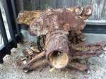
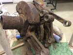
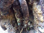
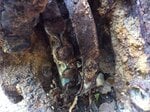
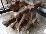
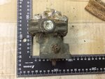
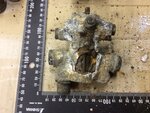
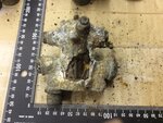
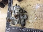
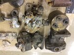
The part on the left is part of the engine casing, probably off the rear case, that includes the drive shaft for the part on the right. The part on the right appears to be a small hydraulic pump or similar. Maybe water/meth pump? Or a gun synchronizer?

The fabric substance is probably the remains of a gasket.

I would suggest that you look for good clear photos of all the likely engines suggested by Shinpachi and try and locate the part on the engine and come back to the site then. Apart from Shinpachi there are not many people who are highly knowledgeable about Japanese engines but the basics of all engines are similar and all countries followed similar conventions in design so even someone with a good hands on knowledge of US/British/European knowledge of engines will be able to identify most items.

You must remember that an Homare "x" and Homare "y" will have many differences so if the part is not on the "x" it may be on the "y"

The picture below comes from this book and the English translation was graciously provided by Shinpachi.
View attachment 563934

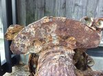
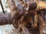
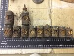
The part in post 35 may be the item arrowed if the engine is a Homare 21. The distinctive domed nut is often used on hydraulic pumps and injection pumps to cover and lock the pressure regulator adjustment
View attachment 563933


________________________

Thank you very much for your information Mr. MiTasol, I will also look more on Homare Type 21.
 
Nakajima Mk 1 hydraulic pump

Hydraulic pump first - there is no adjustable pressure regulator visible on that technical drawing. Only a fixed internal one.
1576389698744.png


Do you have any drawings of the Fuel Injection system Shinpachi?

The only common left right electrical component is the magneto ignition with the third port being the common earth wiring, normally at the switch end. This component has a very light flange with only two screws which suggests it is not part of the magnetos themselves as they must be waterproof against rain travelling at high speed. This could be the back of the cockpit ignition switch or part of a firewall junction box. A photo showing the inside may help in determining what it is.

Below is one type of American booster coil (shower of sparks) similar to the one in several of the posts above.
1576388144665.png
 
Hydraulic pump first - there is no adjustable pressure regulator visible on that technical drawing. Only a fixed internal one.
View attachment 564032

Do you have any drawings of the Fuel Injection system Shinpachi?

The only common left right electrical component is the magneto ignition with the third port being the common earth wiring, normally at the switch end. This component has a very light flange with only two screws which suggests it is not part of the magnetos themselves as they must be waterproof against rain travelling at high speed. This could be the back of the cockpit ignition switch or part of a firewall junction box. A photo showing the inside may help in determining what it is.

Below is one type of American booster coil (shower of sparks) similar to the one in several of the posts above.
View attachment 564031


Is this might be from B-29 ?
 
________________________

Thank you very much for your information Mr. MiTasol, I will also look more on Homare Type 21.


Given that Shinpachi thinks it is more likely to be a Nakajima Ha-5 or derivative photos of those would also help, again remembering that the derivatives will have significant differences.

There are a number of Japanese aircraft manuals on the forum at Manual Index - Japan and most have excellent technical drawings which occasionally show engine details.

There are no Japanese engine manuals that I know of though

This schematic diagram from the Ki-43 manual shows the ignition switch and wiring
1576391229115.png
 
Is this might be from B-29 ?

I am fairly confident the one you photographed has enough variations to be from a Japanese aircraft though these may be just a result of damage. I am not sure if the B-29 had an ignition boost coil - they tended to be used more with inertia starters and lower powered starters on big engines. I do not have a B-29 parst manual to be positive on what it was fitted with.
 
Try this web site because many of the aircraft manuals come from this site which is very difficult for non Japanese writers to search. They almost certainly have engine manuals as well so if you find any (or airframe or component manuals that are not on the ww2aircraft Japanese manuals page) please post copies here. We all come to learn and to help each other so I am not the only person who will appreciate them. As the hydraulic pump that Shinpachi posted shows some of the manuals do have material that may be relevant.
1576392753740.png


Some, if not all, of the manuals are from microfilm copies and some are printed as negatives so are hard to read but can be reversed which I find makes them easier to read

1576393957348.png

1576393920027.png
 
Last edited:
Checked B-29 wiring diagrams and yes they have a booster coil system but I have no way of knowing if it is the type shown above or the type below without a parts catalogue. I woudl strongly suspect the one shown below as that did not require an earth wire (there is none shown in the wiring diagram) and was almost universal on later aircraft.
1576394868531.png
 
Finally, What is this engine?
Sakae or Kinsei

Also these parts too
 

Attachments

  • 1kr_20az.jpg
    1kr_20az.jpg
    201.3 KB · Views: 40
  • 1 (2).jpg
    1 (2).jpg
    716.4 KB · Views: 35
  • D6Qj6gFUEAA0bnO.jpg
    D6Qj6gFUEAA0bnO.jpg
    254.8 KB · Views: 30
  • D7yiGZ_UYAAAzYq.jpg
    D7yiGZ_UYAAAzYq.jpg
    179.8 KB · Views: 36
  • EfLowacT.jpg
    EfLowacT.jpg
    190.6 KB · Views: 35
  • FkU1peqv.jpg
    FkU1peqv.jpg
    179.8 KB · Views: 31
  • fn_aKmIM.jpg
    fn_aKmIM.jpg
    184.8 KB · Views: 34
  • gNoej9Qp.jpg
    gNoej9Qp.jpg
    201.3 KB · Views: 37
  • Hc4fKmLb.jpg
    Hc4fKmLb.jpg
    176.4 KB · Views: 30
  • lRCBHL16.jpg
    lRCBHL16.jpg
    186 KB · Views: 26
  • m4EgcJpQ.jpg
    m4EgcJpQ.jpg
    180.1 KB · Views: 35
  • QMjOHvFA.jpg
    QMjOHvFA.jpg
    181.9 KB · Views: 27
  • ReK_MYdx.jpg
    ReK_MYdx.jpg
    172.6 KB · Views: 40
  • YGJDr3Xl.jpg
    YGJDr3Xl.jpg
    179.8 KB · Views: 30
  • 1 (3).jpg
    1 (3).jpg
    615.3 KB · Views: 28
  • 8 (1).jpg
    8 (1).jpg
    686.8 KB · Views: 30
  • 9 (2).jpg
    9 (2).jpg
    712.3 KB · Views: 21
  • 9 (3).jpg
    9 (3).jpg
    614.7 KB · Views: 29
  • 13 (2).jpg
    13 (2).jpg
    664.7 KB · Views: 46
  • 2 (3).jpg
    2 (3).jpg
    581.4 KB · Views: 30
continue
 

Attachments

  • 10 (1).jpg
    10 (1).jpg
    688.1 KB · Views: 41
  • 14 (1).jpg
    14 (1).jpg
    764.4 KB · Views: 34

Users who are viewing this thread

Back