Navigation
Install the app
How to install the app on iOS
Follow along with the video below to see how to install our site as a web app on your home screen.
Note: This feature may not be available in some browsers.
More options
You are using an out of date browser. It may not display this or other websites correctly.
You should upgrade or use an alternative browser.
You should upgrade or use an alternative browser.
1/48 Classic Airframes Boeing P-12E
- Thread starter Grant Barr
- Start date
-
- Tags
- 1/48 boeing p-12e yellow wings
Ad: This forum contains affiliate links to products on Amazon and eBay. More information in Terms and rules
More options
Who Replied?fubar57
General
Moving along nicely Grant
Crimea_River
Marshal
Great work Grant. For the rigging, I would recommend that you visit a sewing shop and see if you can snap up some of this:

It's very fine and elastic which makes for easy (ish) installation. Best part is that it's flat, not round.

Description here:
**** DONE: GB-45 1/48 Gloster Gladiator - BoB/Foreign Service
It's very fine and elastic which makes for easy (ish) installation. Best part is that it's flat, not round.
Description here:
**** DONE: GB-45 1/48 Gloster Gladiator - BoB/Foreign Service
- Thread starter
- #24
Grant Barr
Senior Airman
Awesome - thanks Andy! Next time I head into town I'll see if I can source some. If not, it might be a case of scouring the interwebs... Cheers!For the rigging, I would recommend that you visit a sewing shop and see if you can snap up some of this:
Good work so far!
- Thread starter
- #26
Grant Barr
Senior Airman
Still working on clean up and fit of various parts. I've managed to remove the mold fill lugs from the inside of the engine cowl and am quite happy with how even the internal surface looks. Given the build for the resin engine relies on the cowl to dictate size and fit of the cylinders I thought it will be important to keep this as "clean" as possible.
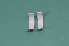
The end block has been added to the gun channels and some installation "stubs" fitted in anticipation of adding the gun tubes. These are simply 0.4mm brass tubes that will fit inside the 0.6mm tubes that I will be using for the guns.
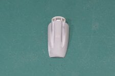
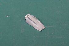
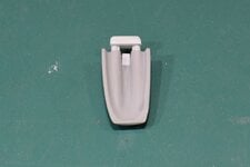
The next two photos show mocked up fitting of the gun tubes and the whole gun panel to the fuselage. I have not been able to source any photos which show detail around how the gun tubes exit the fuselage and extend down the channels. Both the look of the exits and the lengths of these tubes are my best guesses and may well be totally wrong!
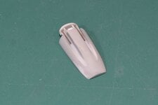
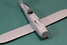
Looking at the gun tubes in place makes me question whether they are too small in diameter. The guns themselves are 0.303's and scaling 0.6mm tube should make it large enough for the tubes, but they just don't quite look right. Maybe it's also a function of the excessively deep channels? Unsure…
As always, thanks for stopping by with comments and feedback.

The end block has been added to the gun channels and some installation "stubs" fitted in anticipation of adding the gun tubes. These are simply 0.4mm brass tubes that will fit inside the 0.6mm tubes that I will be using for the guns.


The next two photos show mocked up fitting of the gun tubes and the whole gun panel to the fuselage. I have not been able to source any photos which show detail around how the gun tubes exit the fuselage and extend down the channels. Both the look of the exits and the lengths of these tubes are my best guesses and may well be totally wrong!


Looking at the gun tubes in place makes me question whether they are too small in diameter. The guns themselves are 0.303's and scaling 0.6mm tube should make it large enough for the tubes, but they just don't quite look right. Maybe it's also a function of the excessively deep channels? Unsure…
As always, thanks for stopping by with comments and feedback.
Lovely work so far!
- Thread starter
- #29
Grant Barr
Senior Airman
Moving along at a reasonable pace now.
Again, I've done lots of work but not much of it shows. Cleaning up more parts and doing a whole bunch of dry fitting seem to be the core tasks at this stage.
The horizontal stabilisers have now been fitted, along with the upper nose panel. Both will require a bit of clean up and some filling to make sure it all looks OK. I've managed to destroy some of the panel lines on the nose and some of these, especially those around the gun channels, will be very tricky to reinstate. I'll have to think a bit more about how best to achieve this.
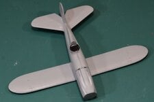
They look reasonably straight from front on, and you can see where the gun mount block helps to fill the large holes created by the nose panel.
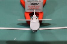
I also took another shot from the rear – mostly to see how much of the cockpit is now visible. The IP is quite visible, so now I am glad that I spent some extra time scratch building it.
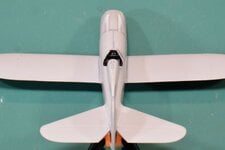
There remains a lot of work in cleaning up parts, reinstating panel lines and making sure everything fits together appropriately. I think the next major task once the panel lines are restored will be to install the outer and cabane wing struts. As noted in an earlier post, they are all the incorrect length and will require some cutting to get it right. The question will be – how much do I need to cut off each piece?
Thanks again for checking in and feedback/reactions.
Again, I've done lots of work but not much of it shows. Cleaning up more parts and doing a whole bunch of dry fitting seem to be the core tasks at this stage.
The horizontal stabilisers have now been fitted, along with the upper nose panel. Both will require a bit of clean up and some filling to make sure it all looks OK. I've managed to destroy some of the panel lines on the nose and some of these, especially those around the gun channels, will be very tricky to reinstate. I'll have to think a bit more about how best to achieve this.

They look reasonably straight from front on, and you can see where the gun mount block helps to fill the large holes created by the nose panel.

I also took another shot from the rear – mostly to see how much of the cockpit is now visible. The IP is quite visible, so now I am glad that I spent some extra time scratch building it.

There remains a lot of work in cleaning up parts, reinstating panel lines and making sure everything fits together appropriately. I think the next major task once the panel lines are restored will be to install the outer and cabane wing struts. As noted in an earlier post, they are all the incorrect length and will require some cutting to get it right. The question will be – how much do I need to cut off each piece?
Thanks again for checking in and feedback/reactions.
Last edited by a moderator:
fubar57
General
Doing some good work Grant
Vic Balshaw
Major General
Good progress Grant. 
Crimea_River
Marshal
Sounds like you need some decent scale drawings to figure out the strut lengths Grant. I had a similar but not as bad issue on my Gladiator build in one of the GBs and ended up building a jig to hold the upper wing where it was supposed to be so I could work on the struts.
As for the 303s, I gotta think there was a cooling jacket over the barrel that would add considerably to the diameter. I have drawings of British Brownings somewhere and recall that the jacket was tapered. It was well over an inch in diameter though.
Let me know if you want more details on this
As for the 303s, I gotta think there was a cooling jacket over the barrel that would add considerably to the diameter. I have drawings of British Brownings somewhere and recall that the jacket was tapered. It was well over an inch in diameter though.
Let me know if you want more details on this
fubar57
General
PM sent

- Thread starter
- #35
Grant Barr
Senior Airman
Thanks Andy. Geo has just sent me through some more information on the P-12. If I can't find anything in that, I will take you up on your offer. Cheers.Sounds like you need some decent scale drawings to figure out the strut lengths Grant. I had a similar but not as bad issue on my Gladiator build in one of the GBs and ended up building a jig to hold the upper wing where it was supposed to be so I could work on the struts.
As for the 303s, I gotta think there was a cooling jacket over the barrel that would add considerably to the diameter. I have drawings of British Brownings somewhere and recall that the jacket was tapered. It was well over an inch in diameter though.
Let me know if you want more details on this
Good work so far!
T Bolt
Colonel
Some real nice work there Grant
- Thread starter
- #38
Grant Barr
Senior Airman
Progress has slowed in the build up to Christmas, however I have managed to do some work.
Time for some struttery!
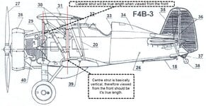
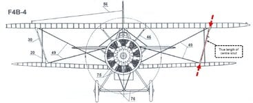
I had sourced some 1/48 scale line drawings of the F4B some time ago (unfortunately I can't recall where I got them – intraweb somewhere, but they are tagged with the drafter name – N. Okolelov). The F4B-3 is reasonably close to the P-12E, especially in terms of general layout of wings, struts and tailplanes, so I used this (and the F4B-4) as a basis to determine what the actual outboard strut length should be. I initially had a concern that I would not be able to determine what the true length of the strut would be, but after establishing the centre post is basically vertical, it is then easy to use the front view as an accurate representation of it's true length.
The cabane struts were easier in establishing that the front view should be the true length, but the line drawing does not give a fuselage profile at the point the strut mounts from the fuselage and is therefore a series of trial and error to get it correct.
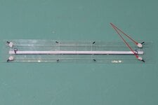
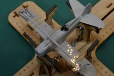
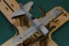
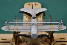
Now having some dimensions to work with I set about creating a template to assist in aligning the struts once I started to put them into place. Like I had done before for a biplane build a while back, I used clear acetate from some packaging and set out the centre points for locating the struts. To keep the acetate straight, I CA glued a length of sprue as you can see on the photo below. This allowed me to set about fitting both sets of struts.
You can also see my high-tech solution to hold bits in place as I jiggle parts into alignment – blu-tack! Very handy when you need three or four hands.
As the struts (unhelpfully…) have no locating pins and are just butt joins to the wings, I decided some brass pins would be the best solution. Once these were fabricated and the locating holes drilled into the upper surface of the lower wing, I was able to dry fit the outboard struts to determine their correct angles as you can see in the following shots.
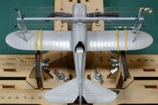
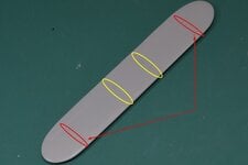
The jig also serves as a guide for the placement of the locating pin holes in the lower side of the top wing. Both the outboard and cabane strut holes are highlighted in this shot and the arrows indicate where I have marked the locations for the rigging wires.
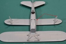
This next shot shows the outboard struts have been fixed into place and the cabane struts have been dry fitted to the upper wing. Also indicated with the arrows are the brass pins inserted for the cabane struts to the fuselage and the outboard struts to the upper wing.
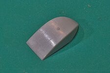
In addition to all the work with struts has been ongoing clean up and fettling of other parts. The underside fuel tank panel has been cleaned up to fit properly under the fuselage and wing, but the panel is almost too bland. Photos of museum aircraft indicate that rows of rivets are quite prominent. As such I broke out the pinwheel to add some rivet detail to this tank – the photo below has been tweaked a bit to bring the fine detail to light.
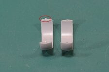
Finally, I have started work on getting the engine parts cleaned up, starting with the engine cowl. This cowl ring is pivotal in getting the engine assembled to the correct dimensions. Looking at the two pieces the first thing that worried me was the fact there is, again, only a butt join holding it all together. To make it a more positive fit and make sure it aligns properly I have inserted some 0.75mm styrene rod to serve as locator pins. This should go some way to both help with panel alignment and to give a stronger joint with more connecting surfaces for the glue to bind to.
That's pretty much all I have in terms of a progress update for now. As always, thanks to all who drop by for a look.
Time for some struttery!
I had sourced some 1/48 scale line drawings of the F4B some time ago (unfortunately I can't recall where I got them – intraweb somewhere, but they are tagged with the drafter name – N. Okolelov). The F4B-3 is reasonably close to the P-12E, especially in terms of general layout of wings, struts and tailplanes, so I used this (and the F4B-4) as a basis to determine what the actual outboard strut length should be. I initially had a concern that I would not be able to determine what the true length of the strut would be, but after establishing the centre post is basically vertical, it is then easy to use the front view as an accurate representation of it's true length.


The cabane struts were easier in establishing that the front view should be the true length, but the line drawing does not give a fuselage profile at the point the strut mounts from the fuselage and is therefore a series of trial and error to get it correct.
Now having some dimensions to work with I set about creating a template to assist in aligning the struts once I started to put them into place. Like I had done before for a biplane build a while back, I used clear acetate from some packaging and set out the centre points for locating the struts. To keep the acetate straight, I CA glued a length of sprue as you can see on the photo below. This allowed me to set about fitting both sets of struts.

You can also see my high-tech solution to hold bits in place as I jiggle parts into alignment – blu-tack! Very handy when you need three or four hands.
As the struts (unhelpfully…) have no locating pins and are just butt joins to the wings, I decided some brass pins would be the best solution. Once these were fabricated and the locating holes drilled into the upper surface of the lower wing, I was able to dry fit the outboard struts to determine their correct angles as you can see in the following shots.


The jig also serves as a guide for the placement of the locating pin holes in the lower side of the top wing. Both the outboard and cabane strut holes are highlighted in this shot and the arrows indicate where I have marked the locations for the rigging wires.

This next shot shows the outboard struts have been fixed into place and the cabane struts have been dry fitted to the upper wing. Also indicated with the arrows are the brass pins inserted for the cabane struts to the fuselage and the outboard struts to the upper wing.

In addition to all the work with struts has been ongoing clean up and fettling of other parts. The underside fuel tank panel has been cleaned up to fit properly under the fuselage and wing, but the panel is almost too bland. Photos of museum aircraft indicate that rows of rivets are quite prominent. As such I broke out the pinwheel to add some rivet detail to this tank – the photo below has been tweaked a bit to bring the fine detail to light.

Finally, I have started work on getting the engine parts cleaned up, starting with the engine cowl. This cowl ring is pivotal in getting the engine assembled to the correct dimensions. Looking at the two pieces the first thing that worried me was the fact there is, again, only a butt join holding it all together. To make it a more positive fit and make sure it aligns properly I have inserted some 0.75mm styrene rod to serve as locator pins. This should go some way to both help with panel alignment and to give a stronger joint with more connecting surfaces for the glue to bind to.

That's pretty much all I have in terms of a progress update for now. As always, thanks to all who drop by for a look.
Vic Balshaw
Major General
Very nice steady progress Grant, you have taken your time with some meticulous work. 
Users who are viewing this thread
Total: 1 (members: 0, guests: 1)
