3D Model B-33 Super Marauder (XB-33A)

Ad: This forum contains affiliate links to products on Amazon and eBay. More information in Terms and rules

Very interesting idea for a plane. As a practicality, a lot plane for such a small bomb load.
I agree it's a very interesting aircraft (and quite a looker!). Regarding the bombload and weight... In a way, yes, it is a lot of plane for a small bombload. I don't remember if I have clearer diagrams, but that (admittedly hard to read) bombload diagram does list 24 x 500 lb, 8 x 1000 lb and 6 x 2000 lb loads, which for a plane that size isn't that bad, but is still a bit substandard. iirc the increasing weight of the design (it gradually went from a 94 ft wingspan to a 134 ft wingspan) was a reason in its cancellation. It's the same bomb capacity as a Lib in a time of Superfortresses and Dominators; just really not very necessary. I don't recall if its range rivaled the Lib or not.
 
Hey all, hope you're doing well. I've done a lot of research into the early short wing Marauders lately as they're some of my favorite aircraft, and have started work on one (B-26-MA, to be specific) but that has been incredibly frustrating, so I'm shelfing that idea for now. I still wanted to work on something, and since I can't work on the B-32 either, I decided to work a bit more on this bird.

Finally started a process I've tried and failed several times in the past: redesigning the engine nacelles. Over the last two days I believe I've finished the hardest part of doing so, which was reshaping the air "scoops" and the oil cooler inlet so that they blend smoothly into the nacelle and have more realistic construction. You can compare the old design vs the new one in the two images below.
11 old.PNG11.PNG

Now, the work on the nacelle is not done. For some reason that I cannot remember, I seem to have made the entire nacelle's skin 2 inches thick, which seems rather excessive. I have no way of knowing how thick the sheet metal they used in real life was, but 1/4 to 1" seems to make more sense. I'm not sure how I'll approach this, if I'll change sections of it, the whole thing, or none of it.

Regardless of skin thickness, there's more work to be done. I now have to make the section the nacelle immediately aft of the cowl flaps thinner, to allow for a gap when the cowl flaps are in the 0 degree position (Martin commonly made the "fully closed" position for the cowl flaps be -5 degrees, unsure if the cowl flaps themselves were able to move in this manner). I'm also not satisfied with how the wing currently blends into the nacelle, it seems too steep and doesn't make much sense. Modifying this might also require changes to the flaps, but this wouldn't be too difficult, just tedious.

I also need to decide (and model) what the layout is inside the engine nacelle, and figure out what parts would be different panels and where they intersect. I originally thought the entire nacelle forward of the firewall including the engine cowling could be one singular sub-assembly, as is the case in the B-26, but am now considering the possibility that the cowling is a separate piece. Open to suggestions on that front.

Cheers,
-Matt
 
Cool. If you're sticking with the B-26 Greg Boeser Greg Boeser will be interested in this
Nice, I'll take any help I can get! I do plan on sticking to it, the short wing B-26 has been on my to-do list since around 2016. I've gathered a lot of manuals and diagrams, basically anything short of the original manufacturer's blueprints, but that still leaves a lot of guesswork in key areas, such as the actual shape and size of the aircraft's main bulkheads, and location of the attachment points for the landing gear and flap linkages. I do have some pictures of the linkages themselves thanks to Andrew Boehly from the Pima Air museum, and have quite a few useful pictures taken from walk-arounds of Kermit Week's aircraft, and restoration photos of the aircraft in the MAPS museum (I plan on reaching out to them when I can, they are currently closed). I feel I should probably make a separate thread if I am to start documenting/discussing that aircraft, so I might do that later. That being said, my inbox and email are always open!
 
Now, the work on the nacelle is not done. For some reason that I cannot remember, I seem to have made the entire nacelle's skin 2 inches thick, which seems rather excessive. I have no way of knowing how thick the sheet metal they used in real life was, but 1/4 to 1" seems to make more sense.

Most likely 0.040 for the skin thickness but possibly 0.050. Many cowls were only 0.032.
I dont have any repair manuals for the B-26 but the B-25 repair manual has these skin thicknesess for the naccelles. They have no cowl thicknesses listed.
1589317455104.png
 
Most likely 0.040 for the skin thickness but possibly 0.050. Many cowls were only 0.032.
I dont have any repair manuals for the B-26 but the B-25 repair manual has these skin thicknesess for the naccelles. They have no cowl thicknesses listed.

Thanks for the input! Seems like I've overestimated the thickness yet again. I suppose that's what happens when you use wooden mock-ups as reference. Depending on how work progresses on the plane, I'll try to bring the thickness down. There's a lot to fix in the XB-33, but not all of it really worth fixing, so I'm gonna do what I can in the near future to pick my battles.

The cowl flaps, for example, will look a bit off. I originally picked how many sides the engine would have (since cylinders aren't really possible in models like this) on the basis of making each cowl flap be two-sides/polygons wide, which still seems like a solid approach... but I miscounted and thought the aircraft had 3 cowl flaps per set instead of 4. I can and will make 4, but they won't line up as pretty, because changing the shape would require reworking the entire nacelle and cowling, which would take months.
 
No progress lately as I've found I might have to redo the entirety of the inner wing section, and remake the nacelles, and have been procrastinating on that front by focusing my efforts on the B-26 Marauder instead. Will update this thread when I can.
 
Last edited:
Hi everyone,

I've been working on this bird again for the last few days, after finding a set of higher resolution (mostly legible!) blueprints for the second to last version of this plane.

The Bad
There is a lot to fix, most noticeably the fact that the outer engines are around 4" inboard of where they're supposed to be and that the landing gear attachment points are in the wrong location. There are also countless smaller errors, some worth fixing, some not. I've been putting together a data sheet, much like with the B-26, documenting all the dimensions I can find (and read) and will post that sometime soon and update it when able.

The cause of a lot of the small errors is the fact that the commonly reported aircraft length of 79' 10" is wrong. Or rather, it's correct for 3 versions of the plane, but not the final one. The final version of the plane measures 79' 8.875", having a shortened tail and a lengthened nose.

Because I started work on this model when I was 16 or 17 and barely understood aircraft design, I eyeballed most of the model based on the overall dimensions, sometimes rounding dimensions up or down to what I found a logical. I'm not entirely sure what steps I will take to fix the fuselage yet, but it will be tricky. It's a good thing I didn't start on the interior for the most part.

The Neutral
The aircraft's tires are the wrong diameter in my model, being slightly too large. This is most likely a result of the aforementioned wrongly scaled blueprints and subsequent rounding (as well as not being able to read the blueprints). This isn't a big issue as I was planning on remodeling the wheels entirely anyway, given that the tires look far too round and the wheel hubs look very wrong.

I'm not sure about my design for the landing gear doors, and am considering purchasing photographs of the prototype under construction from the Smithsonian, if they have any, and double-checking. It's my understanding that those can be sent digitally, which is very convenient for me as I'm still stuck outside the US for the time being (Though as far as I'm aware the archives are still closed). Given that I'm going to be rebuilding most of the engine nacelles, fixing the landing gear is now possible without affecting other components.

Thanks to the legible set of blueprints, I now know the airfoil for the main wing, or rather some details of it: NACA 65 series with 22% thickness at the root, 14% thickness at the theoretical tip. This enabled me to make a much more accurate airfoil, and combined with the other dimensions, a much more accurate wing. I won't be posting pictures of it yet because I have yet to cut the wingtips, flaps and ailerons. I'm still unsure as to how I'll accomplish the smooth blending of the wing into the engine nacelles, but am not in a rush to figure it out at the moment. I do not plan on significantly remodeling the stabilizers, not do I have the data to do so. They look very accurate, so at most I might squish and stretch them to match the proper dimensions.

The Good
I've finally finished streamlining the forward nacelle and cowling, and I've cut out cowl flaps! I had no reference for these, so I based them off of the B-26's cowl flaps. They're not entirely accurate to the B-26, but I think they look good enough. The general arrangement drawing shows 3 sets of 4 cowl flaps, but the area between the two top intakes is large enough to accommodate 5 flaps. I went with 5 for now, but might change this later. I copied the movement range from the B-26 as well, so the flaps can move between -5 and +40 degrees. They are shown below in the 0 and 40 positions. I have yet to model proper hinges.
cowl flaps 1.PNGcowl flaps 2.PNGcowl flaps 3.PNGcowl flaps 4.PNGcowl flaps 5.PNGcowl flaps 6.PNGcowl flaps 7.PNGcowl flaps 8.PNGcowl flaps 9.PNGcowl flaps 10.PNG

Using 5 flaps at the top results in greater interchangeability of parts (all 3 sets end up being identical save for an additional flap fitted in the middle of the top set), and in much cleaner and symmetrical streamlining of the top air intakes. However, both the blueprints and the scale model used for wind tunnel testing seem to have 4 flaps in this section. Switching to 4 will require once again remodeling part of the air intakes, so I'm unsure if I will. I'm also not sure what internal equipment (if any) would prohibit the area near the intakes from being used for cowl flaps. Again, photographs might be useful in this area.

What's Next
I'm not sure yet, as there is a lot to do, and it's not clear what the next step should be. I might continue work on the nacelles, work on the landing gear, stabilizer or fuselage, or wait until I can get photographs.

Cheers,
-Matt
 
Hi all,

No significant work on the model, but I'm continuing to research all the aircraft I'm interested in, and found this NACA report based on wind tunnel tests of the XB-33: Tests of Four Models Representing Intermediate Sections of the XB-33 Airplane Including Sections with Slotted Flap and Ailerons - NASA Technical Reports Server (NTRS)

It's an analysis of the wing sections, of different modifications to the flaps to try to improve their efficiency, and a comparison between Frise and Internal Balance type ailerons. I do not know which designs Martin would have chosen to go ahead with, as the only legible 3-view drawings I have are from May 5th of 1942, and the report is dated by NASA as June 1st 1942, and by the report itself as June 4th, 1942. Some of the inboard profiles I have date from 1943, but these are not concerned with the wings.

NACA's recommendations seem to favor reducing the wing's thickness at the root due to very high drag if the surface is roughened, which I think means in icing conditions or if damaged. It also states that the flaps should be mounted slightly higher and aft of their current position. I think they're also saying Condition E would be the best modification to proceed with for the wing flaps based on the results, and that there's very little difference in using the Frise or Internal Balance designs for the ailerons. Given that Martin switched from Frise to Internal Balancing partway through Marauder production, perhaps they would have done the same with the B-33.

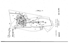
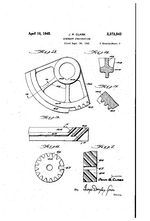
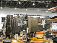
I find Condition F particularly interesting, as Martin does have a 1941 patent for a slotted flap with a moving door, credited to John R. Clark and shown below. Given its date, the patent is older than the report, and the two door designs do not look similar. I'm not sure if any Martin aircraft ended up actually using this design, but the structure the flap is mounted to is very similar to the one used on long-wing B-26s, visible in this photo of Flak Bait's wings:
Wing Flaps B-26B-1 Patent 1.pngWing Flaps B-26B-1 Patent 2.PNG1627751693527.png
To clarify, this door was not mounted on any B-26, and I do not know if it was mounted on the B-33, I'm merely noting the similarities between this wing flap design and the flaps mounted to long-wing B-26s.

It's also worth pointing out that North American's B-25 and XB-28 both did have doors to streamline their wings when the flaps were retracted, the design of which is quite close to Condition F.
 
This model is still very much on hold, but I saw this today and thought it was pretty interesting. At the timecode linked (0:24) there is a photo I hadn't seen before of the B-33 wind tunnel model, and it shows that I got the chin area pretty correct, but have the wrong shape for the oil cooler/engine accessory section of the nacelles.
 

Users who are viewing this thread

Back