- Thread starter
- #41
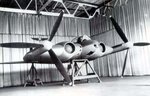
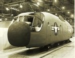
Republic VFX
View attachment 240525
Looks like it might have swing wings...
Some info here:
Republic VFX?
Found this after I posted. I guess I was right about the swing-wing.
Follow along with the video below to see how to install our site as a web app on your home screen.
Note: This feature may not be available in some browsers.
Ad: This forum contains affiliate links to products on Amazon and eBay. More information in Terms and rules
Republic VFX
View attachment 240525
Looks like it might have swing wings...
Some info here:
Republic VFX?
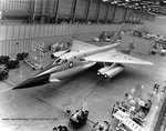
Notice how that F2F appears to have a machine gun on the top wing ?
Shades of WW1.
That's a gun camera. I thought it was a gun also but when researching to build a model, I found out that's where Grumman put the camera's on their Bi-plane fighters.
Ed