Crimea_River
Marshal
Never thought of using Milliput for that. I use lead wire for that application.
Follow along with the video below to see how to install our site as a web app on your home screen.
Note: This feature may not be available in some browsers.
Ad: This forum contains affiliate links to products on Amazon and eBay. More information in Terms and rules
")
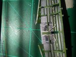
Indeed! I did read through your build a while back on the Monogram p-51. Very nice and I will be referring back to it soon for inspiration if that is ok.The Mustang's wheel wells are a detailer's dilemma.