Airfix 1/48 P-51D

Ad: This forum contains affiliate links to products on Amazon and eBay. More information in Terms and rules

Thank you everyone! The comments and insights are much appreciated.

JKim JKim
Thanks for the tip on the aqua gloss, will give that a try in a future build perhaps as I don't foresee me being able to get to my nearest hobby shop before I complete this one. By the way, I borrowed your tip for your reflective glass from your 1/32 Me-262 build on my own gun sight. I really liked that technique. :)

Crimea_River Crimea_River
No worries Andy, I have indeed planned ahead for the colored lights. I plan to mask them with liquid mask then after everything else is painted, unmask them and paint them with clear green, red and amber accordingly. Awesome picture by the way, will save me a search when it comes time for this detail. Thanks!

So, things are coming together, but slowed down a bit due to filling/sanding and needing to finish some smaller details before proceeding. Here are some pictures showing current status.

0328182244b.jpg

Wings have been glued on and the leading edges filled, sanded and polished. The fit here was very good but I believe I neglected to check the fit of the lower wing/engine transition piece as well as I should have, leaving me with a small lip I had to blend in, especially on the port wing. I believe this to be my fault and not the quality of the kit

0328182244c.jpg

There was a small ledge between the two fuselage halves on the bottom of the radiator intake housing. This was dealt with easily enough with Mr. Surfacer 1000 and some sanding, the resulting lost panel lines rescribed.

0328182245a.jpg

This area was an absolute bear to deal with due to the tail wheel well doors being fixed in place. The problem seems to be that the right hand fuselage half (on the left in this picture) seemed to to have a slight molding defect in that the edge that was supposed to mate to the other half curled slightly inward causing a lip fore and aft of the tail wheel well. This was filled with various applications of milliput (yellowish areas) and Mr. Surfacer 1000 (grey areas). Finally got it smoothed out I think. A coat of primer when all other assembly is completed will tell.

0328182245b.jpg
0328182245c.jpg

These two pictures shows the excellent fit of the upper and lower fuselage panels. A bit of melted plastic oozed out and I will have to reimplement the lost panel lines, but I was otherwise very happy about the fit. Also of note, though I don't have a picture of it, is the fit of the wind screen part when I had done a test fit.. It literally snapped into place and to remove it I had to prise it loose with my fingernails! Perfect fit all around, no gaps, no over hang or any other areas that will need correcting. It is for fear of damaging it upon removal that I don't have a picture of it and I will not put it in place again until final assembly before painting. I doubt I will even use any cement on this part.

0328182246b.jpg

Now, something somewhat puzzling is this. It may be hard to discern, but when looking from the front the vertical stabilizer seems to lean slightly to the left. I tried correcting this by dipping in boiling water and aligning it vertically. The problem with this though was that when viewed from the rear where the rudder would attach, it now had a slight curve and was not straight. I redipped it and put it back where it originally was, slightly leaning. Now, I know the whole fin is offset to port at an angle, the rear terminating at the center of the fuselage. My question then, to those much more familiar with this aircraft than myself, is the vertical stabilizer supposed to have a subtle lean to it? Also, if it is or isn't supposed to, could/would this be caused by the offset tail? Just curious more than anything, because unfortunately if it isn't, there is nothing I can do short of major surgery and I will just leave well enough alone in that case for fear of making things worse than they are.

Now for some fun stuff!:headbang:

0328181538.jpg

My research indicated that the gun sight most likely used on my aircraft was the N-9B-1. Later replacement aircraft that showed up later than the one I will be modelling came from the factory with the newer K-14B sights. Airfix thoughtfully supplies one of each type in the kit, awesome! Thank you Airfix.

So, I started by first clipping off the thick reflector glass. I cleaned up the mold seem which runs vertically around the whole part, and sanded and polished the top area where the lamp lens and reflective glass should be. I wrapped some very thin copper wire around a small punch I have then cut through the resulting coil to make rings. I picked one out and flattened/closed it by pressing down with the flat end of my x-acto knife handle. As shown in the picture, I both secured it and made the lamp lens by applying a drop of Mod Podge dimensional magic. Very nice result I think.
0328182243a.jpg

0328182243.jpg
0328182244a.jpg

Here is the N-9 sight painted and finished. I painted the whole thing MM Acryl flat black (except for the lens) then highlighted edges with a light dry brushing of Polly Scale neutral grey. I painted the head pad on the front with burnt umber then went over it with a dark rust color to make it stand out better. The reflective glass I cut from a piece of clear plastic from the discarded packaging from a cell phone. I borrowed JKim's idea from his current build and painted the edges a mix of MM Acryl clear green and blue. There is an on/off toggle switch on the left side of the gun sight. I punched a disc from some flash in my scrap plastic bin (because it is paper thin) then added the switch from a microscopic piece of copper wire. I painted the disc silver and the switch neutral grey. I am super happy with the result.

Now, final picture and something that almost made me fall out of my chair when I noticed it.:eek:

0328182159.jpg

This is a pilot's eye/head-on view of the gun sight. With it angled just right, the light reflects off of the gun sight lamp lens and onto the reflective glass, just like the real thing! How cool is that!\\:D/ 
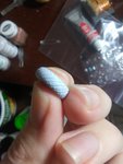
Proof that I must have built it correctly.;)

That's all for now, more soon.
Until next time, happy modelling!
-Chad
 
Last edited:
Excellent work on the gun sight - a really tricky job on such as small item.
Not sure about the fin, but I doubt it should lean over. It's possibly some slight warping of the parts, and I think I'd just leave it as it is, as it's not that noticeable unless mentioned.
 
With Terry, and I love the gun sight. Well done!

BTW, I know you want to keep this OOB as much as possible but in reality there would never be so many rivets seen on the wings as these were filled, primed, and painted over with aluminum dope at the factory.
 
Wow! that is awesome work with your gunsight. :jawdrop:
The inspiration that John offered us with his gunsight in his 1/32 Me262, it was enough, but now with what you did in 1/48, I am convinced that you are "one more" of the hopless we live and we are in the pavilion of the "sick by the detail", ... and you are one of those who are very delicate! :nailbiting:

Chad is your name?, I will be attentive to your progress Luftace43. Very interesting work so far.

Saludos desde México :thumbup:
Luis Carlos
SANCER
 
Awesome work on the gunsight! I think the small ring on the optical element makes a big difference and I'll keep that in mind for my next gunsight. I love the fact that the glass actually reflects the optical element! Scale is a weird thing. Your 1/48 gun sight looks bigger than my 1/32 Revi.
 
Thank you everyone! I'm really glad you liked the gun sight. For such a simple piece, the outcome has to be one of my favorite parts of this build. It didn't take much effort and was fun to do the few modifications to it.

Crimea_River Crimea_River
As far as the rivets and panel lines on the wings go, I'm still undecided but leaning towards not puttying. Part of me wants to be accurate, the the other part cringes at covering up nice details. I'll make that decision sooner than later. :-k

Been slow going, trying to make sure everything is in order before doing any primer or painting. (Read as procrastinating :lol:) I have all the major assemblies together so this is what she looks like right now.
0405182154.jpg

I rescribed all panel lines that were lost during assembly and sanding. Finally got myself a real scriber and I am super happy with it. Made the task so quick and easy I was literally looking around for anything else I could possibly scribe when I was done with the few panel lines that needed attention.:laughing6:

Here's my scriber and new JLC razor saw. Very handy. Dunno how I've built models without them thus far.
0405182156.jpg


And here is part of the reason for my slow progress.
0402182130.jpg
0402182130a.jpg

The wheels in the kit have no tread molded on the center of the tires. I thought I would try to fix this by cutting in the pattern myself with an X-Acto "fine tooth" saw. Well, this tool is much too clumsy for this task and can be likened to using a chainsaw for custom cabinetry. Disgusted with the results and possibly having ruined the wheels, I stepped away after making only a few really ugly cuts. I didn't want to buy the Brassin wheel set, but that was looking like my most likely option for the result I wanted. Long story short, I got to comparing prices between the wheel set and a micro saw. Figured the few extra bucks on the saw would be a wiser investment than on a set of wheels that I could only use once. So, ordered the saw and scriber last week and didn't do anything else until they showed up this past monday. Best purchase so far!

0402182130b.jpg

Initial tests with the new micro saw seemed very promising indeed. Hope had returned!

0405182152a.jpg

The final result after all tread pattern reestablished and cleaned up with light sanding and tamiya extra thin cement. Pretty good. Did I mention I really like this saw? ;)

I also cleaned up the exhaust stacks and drilled them out. Initial test fitting showed that they stood proud of the surface instead of sitting slightly recessed inside the cowl panel, so I trimmed and sanded the mating surface on the back until they did so. I don't have picture of them before I did this, but to give you an idea, the back side is now notched/squared off where as it used to be the length of the whole piece.
0405182153.jpg


And last thing for this update is the rear piece for the spinner. There is a maintenance access panel that is entirely absent on the kit part. I made a template out of dymo tape and attempted to scribe this with a needle. Third try and this the result. A little crooked, but good enough for me this time around. Curves on curves are a pain in the posterior to scribe, let me tell ya. :confused:
0405182155.jpg

Before
0405182155a.jpg

After

That's it for now, I have another update in just a few minutes, so check back soon. It may be interesting to see. ;)

Chad
 

Attachments

  • 0402182130a.jpg
    0402182130a.jpg
    417.8 KB · Views: 80
Ok, now the other update as promised. This is an ambitious task of sorts, and seeing it as an experiment, I did not initially take pictures of the "how" I went about this. I did however go back and take a few photos to demonstrate the general idea. So, here it is, custom built 110 gallon drop tanks.

0405182144.jpg

I started by gathering references found on the web the dimensions of these tanks. Most of my information comes from here:
Anyone got the 1/32 Tamiya P-51D/K in the stash?

I converted the measurements from 1/32 to 1/48 and laid them out on paper with pencil and ruler. Next, I made a core from household aluminum foil, compressed as much as possible. The actual one I used was just a little wider and longer and fit my drawing a little closer than shown here.

0405182150.jpg

Next I used Super Sculpey oven bake clay and covered the foil core. I then carefully sculpted the clay using my fingers so the shape was near as perfact as I could get to my template. The foil core serves two purposes. It gives the sculpt rigidity so it doesn't deform as much as well as being a filler thus needing to use a minimum of clay. Perhaps a third point is that it does make it a little lighter weight as well. After I was satisfied, I baked it at 275 F for 15 minutes according to the instructions. This is a staged photo as well, so it neither has the core nor is quite as refined as my actual sculpt.

So, after baking and allowing to cool for about an hour, I used a sanding stick to get the surface evened out. Couldn't see this with the naked eye, but sanding quickly reveals high and low spots. Once all looked uniform, I applied two coats of Mr. Sufacer 1000 to the entire tank, allowing an hour cure time between applications. Finally, I sanded everything smooth again and polished it up using progressively finer sanding films. After all was smooth, I marked the center line of the tank all the way around horizontally with a pencil. I then used milliput yellow/grey to make a long, very thin snake of putty. I applied this carefully along my pencil line to create the lip of the two tank halves. After allowing the putty to cure and become firm, I ran a bead of CA glue around the putty to ensure it stays in place. That's where I am at now. I still need to add the filler cap and attachment points, but I am going to let the milliput cure overnight before doing so.
0405182150a.jpg
0405182151.jpg
0405182150b.jpg


And finally a comparison of my tank compared to the kit 75 gallon tanks for an idea of size.
0405182152.jpg


Once this is finished, it will be a master for making a mold and making resin copies. Hope you liked this little adventure.

Chad
 
Good stuff, and nice wok on the master for the tanks.
Those razor saws are great - got one a few years back, and don't know how I managed without it. I've also used it for doing the treads on tyres, and for panel lines, using the tip of the 'fine' edge on the blade.
 
Great work there Chad. I used a similar technique for making a wingtip tank mould for a CF-5 out of wood but never got around to casting the resin parts. I assume that you will be making two resin halves and then gluing them together.
 
Looking good, great stuff Chad.
Somewere in time I'll create muy own resine pices. But first I have yo learn how to do them and practice. o_O

Saludos :thumbup:
 
Thank you all for the encouraging feedback. The endeavor continues.

0406181435a.jpg

I drilled a hole of appropriate diameter for the filler cap.

0406181434.jpg

For the filler cap, I first punched a styrene disc, then a disc from aluminum of a smaller diameter. With my xacto knife I cut the aluminum disc in half then removed a small sliver from one side. I glued the two halves with CA to the styrene disc, leaving a gap where the sliver had been cut away. With the sliver, I cut two small squares and placed them between the aluminum disc halves to form the hinges.

0406181439.jpg
I filled in part of the hole with milliput to give the cap a positive place to be secured.

0406181441.jpg

I placed a dap of CA on the milliput then pressed the cap into place.

0407181906a.jpg

I then sand the top part of the tank flat and added the brackets for the mounts from styrene sheet. I drilled out where the four bolts go on each bracket with a #80 drill bit.

I then gave the whole thing a couple coats of Alclad black primer/microfiller with some sanding in between coats.

0408181443.jpg

I made a mold box using Legos and lined the bottom with plasticine clay. I built it up around the master and smoothed it out as best I could. I used a Lego stud to create keys so the other mold half will lock into place without slipping when used for casting. In theory it should hold together like legos! :laughing6:

0408181459.jpg

I mixed up 2 oz of silicone according to the directions then carefully poured it into one corner of the box allowing it to cover the master as the volume rose to minimise air bubbles. Now we wait for 3 hours until I can remove the clay and pour the second half. More to come soon, thanks for looking in.

Chad
 
Good stuff. I like the key idea and never thought of making the part in one pour. My approach would have been to make two halves but I like your idea.
 
Crimea_River Crimea_River
Thanks Andy! I have a little experience making two part molds of some 1/8 scale figures I have sculpted in the past, so this seemed pretty straight forward in comparison. I did lots of research a few years ago when I was casting my figure sculptures and making keys was one of the interesting tips I latched onto. I'm hoping there will be less cleanup and sanding as opposed to if I had molded two separate halves.

Also, if anyone knows of any decals in 1/48 for 110 gallon drop tanks, I'm all ears. I don't want to use the kit decals because I don't like the idea of someone actually reading them and they saying "75 gal. Capacity"
 

Users who are viewing this thread

Back