B-25C/D Exhaust Stub Question

Ad: This forum contains affiliate links to products on Amazon and eBay. More information in Terms and rules

Crimea_River

Marshal
46,328
14,417
Nov 16, 2008
Calgary
Looking to possibly convert my Accurate Miniatures B-25B to a D which seems doable. However, the only stumbling block I have at the moment is understanding the configuration of the exhaust stubs. The B collected the exhausts from all the cylinders into a header that discharged through a single port on the outboard side of the nacelle behind the cowl flaps. Later B-25's had individual stubs that exited through the cowl - not interested in those and there are lots of pics on the net. However, I'm looking for details of the early C/D arrangement where the single outlet of the B was replaced with multiple outlets behind the cowl flap with flame dampers like in this screen grab from the B-25C/D Flight Manual found on this site:

Capture.JPG

So, for 14 cylinders, how are these arranged? I see clusters of 4 and 3, which makes sense but how are these clusters arranged around the nacelle? How many clusters are there? Does anyone have good pics or plans of these as I have not found any on the net. Thanks!
 
Looking to possibly convert my Accurate Miniatures B-25B to a D which seems doable. However, the only stumbling block I have at the moment is understanding the configuration of the exhaust stubs. The B collected the exhausts from all the cylinders into a header that discharged through a single port on the outboard side of the nacelle behind the cowl flaps. Later B-25's had individual stubs that exited through the cowl - not interested in those and there are lots of pics on the net. However, I'm looking for details of the early C/D arrangement where the single outlet of the B was replaced with multiple outlets behind the cowl flap with flame dampers like in this screen grab from the B-25C/D Flight Manual found on this site:


So, for 14 cylinders, how are these arranged? I see clusters of 4 and 3, which makes sense but how are these clusters arranged around the nacelle? How many clusters are there? Does anyone have good pics or plans of these as I have not found any on the net. Thanks!
These are the flame suppressors first introduced in North Africa, after the single exhaust on the early C/D models have proved "dangerous" during night missions. To quote veterans' memoirs about the latter: "Our Mitchells were like fireflies in the night and quite visible for the German AA". (quote not exact).
All the single stacks were connected to a collector ring and are not in any particular order with the cylinders:
1ZJcgnT.jpg

Below are both sides of the 2 engines with the individual stacks:
A. Exterior right
yNVE7pU.jpg

B. Exterior left
lXEh7zM.jpg

There are 2 groups of 3 stacks only: one on the left side and one on the bottom of the right side. (Right and left as seen from the pilot's position). All others have 4 stacks.
The first photos I saw with the above details were from the Life-magazine as shown below (those are Dutch Mitchells):
Nfk2O14.jpg

TCd8L2T.jpg

Cheers!
P.S. Sorry, forgot to add the description from a "B-25C/D Repair Manual";
nwLe9IZ.jpg

jfRqDEM.jpg

Note: the collector rings and the stacks WERE NOT mirrored for the 2 engines. Compare the above photo of the left engine (right side) with the right side of the right engine - they are the same. The groups of stacks 4-4-4-3-etc. are always on the right side. The groups of stacks 4-3-4-etc. are always on the left side.
 
Last edited:
:thumbright: Good luck with your model!
Cheers!
Longer term plan Yves. I'm looking at maybe doing B-25D-1 "Dirty Gertie from Bizerte" for the upcoming MTO GB. It's an early D with the above stack arrangement so some scratchbuilding will be needed to convert from the B. I'll also need to add a clear dome over the navigators position which shouldn't be much of a problem. Continuing to research this.
 
Longer term plan Yves. I'm looking at maybe doing B-25D-1 "Dirty Gertie from Bizerte" for the upcoming MTO GB. It's an early D with the above stack arrangement so some scratchbuilding will be needed to convert from the B. I'll also need to add a clear dome over the navigators position which shouldn't be much of a problem. Continuing to research this.
This a/c is one of my favourites, because of the patchy look (even if she was not modified as many of the MTO Mitchells). The name of the a/c comes from a GI song - see below.
Speaking of mods - I believe the AM kit of B-25B is very much the same as the B-25C/D comparing the parts included and you'll find what you need.
As per Norm Avery the single flame dampening exhausts were first incorporated on B-25D-1, s/n 41-29848 and used through a/c s/n 41-30352.
On the other hand air filters have been added to the carburetors starting with the same s/n 41-29848, which changed the appearance of the air scoops - wide and flat. "Durty Gerty" has s/n 41-29896 and the bigger scoops. Note the characteristic "bent" cowl flaps on each side of the scoop:
3293579125_7899cc544f_b.jpg

dmfktiB.jpg

Here is a comparison between early and mid B-25C/D:
Early, small scoops:
BuzXBK4.jpg

Medium and late wide scoops:
etx9k8d.jpg

And here's the song:
zqukTTL.jpg

Dirty Gertie from Bizerte
Hid a mousetrap 'neath her skirtie,
Strapped it to her knee-cap purty,
Baited it with Fleur-de-Flirte,
Made her boyfriends' fingers hurty,
Made her boyfriends most alerte!
She was voted in Bizerte
Miss Latrine for 1930.
Dirty Gertie from Bizerte
Saw the Captain, made ze flirty
Captain zink she verra purty,
Lose his watch and lose his shirty,
Call ze general alerte,
The geendarmes look for Dirty Gertie
From Casablanc' to Gulf of Sirte:
Has anyone seen Dirty Gertie?
Dirty Gertie from Bizerte
Roll zee eyes and make ze flirty,
Wears no chemise and wears no skirty,
Wears wan veil and wan night-shirtie.
All ze soldats in Bizerte
Vant to meet wiz zis here Gertie,
Drink ze toast to Dirty Gertie,
Vas wan cute keed when she's zirty!


*Words by Pvt. William L. Russell*
Cheers!
 
Thanks again CATCH 22 CATCH 22 Yves. I didn't know about the wider scoops so need to look into that. Should be "scratchable". As for having everything I need in the B kit, I don't think that's the case in regard to the needed flame dampers poking out from behind the cowl flaps. Though I haven't taken all of the sprues out of the bag, I see that there is a separate sprue with the single exhaust outlet on the nacelle but I see no evidence of the flame dampers.

I picked Dirty Gertie for the same reason when I came across the above pic. I like the worn desert pink over OD scheme and the nose art should be fairly easy to replicate using my mask cutter. I'll need to cobble together the s/n 's though. I have all the right numerals from the B kit but they seem larger than the ones I'll need. Plenty of time to keep planning.
In fact I wasn't referring to the exhausts when talking of parts in the kit. I don't know a kit of B-25 (in 1:48) having those intermediate flame dampeners. I'm not sure is there any aftermarket though. Sorry for the misunderstanding, I was talking about minor parts included in the AM -B and -C kits one can use.
I have the Academy "clone" of B-25C/D and here are the sprues with the carburetor scoops:
XQe7O4u.jpg

Right-bottom are the small ones, top-middle are the bigger ones etc.
Looking at the parts in the original B-25B kit (seen here):
b25reviewbg_2.jpg

you have the small scoops only.
So it was my mistake assuming the B and C/D kits were the same in their original versions. :mad:
And yes, you're right, the B-version had bigger serials than the later models. You'll need to dig deeper into the spare decals box or find some new decals.
alf-null-problemo.gif

When the time comes for your model please show us what you have and what you need and I'll might be able to help with some parts, decals etc. I have several Revell/Monogram models, old and new, and they could be great donors for what's needed - one never knows....
Cheers!
 
Yep, old thread I know but I'm toying with restarting my B-25 conversion.

QUESTION: As I would like to pose the cowl flaps in a semi-open position, I'd like to know if the staggered configuration seen in the LIFE magazine shots and in the manual excerpt, Fig 215 all in post #2 represent a "natural" flap position. Note how the flaps over the exhaust stubs appear to be opened further than those higher up the cowl.

Anyone know the answer? Micdrow Micdrow ? CATCH 22 CATCH 22 ?
 
Andy,

The exhaust system may be different but the mechanism of actuating of the cooling flaps seems to be the same. It looks like the three top flaps could be opened not too much while these bottom and side ones more. But it came from the difference in the shape of the bulkhead between the firewall and the engine back. The engine was mounted slightly up than the bottom edge of the nacelle. Also most of the air going through the engine was leaving the engine compartment was coming out from the bottom and sides while the top air stream was also used for the carburator if it was cold outside. Anyway it can be noticed that the flap actuators protruding differently around the entire perimeter getting longer from top to the bottom of it.

b25engine_cooling flaps_a.jpg

b25engine_cooling flaps_b.jpg

b25engine_cooling flaps_c.jpg

b25engine_cooling flaps_d.jpg

B-25_engine.jpg

the pic source: the net.
 
Appreciate the info guys thanks. Looks like the openings did vary as part of the design.

Still wrestling with how to make the finger exhausts. Looked at rectangular brass tubing but none I could find on line and in shops are the right size. 3D printing could work but I need to design the stubs and that could take longer than carving them by hand!
 
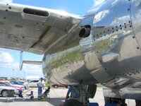
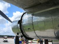
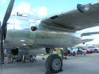
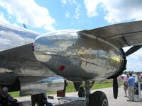
Sorry Andy, Been kind of busy. I have never researched these before on the B-25 though I have read on the exhaust you are talking about but can't find it right now. I know these are not the exhaust you are looking for but what I have so far of pictures I have taken from different B-25's. Still looking but also getting ready for Air Venture as it starts next week. My son comes home Saturday and took the whole week off for work. I thought I had pictures of your configuration on a real B-25 just not remembering where though I will keep looking :)

Pictures below all taken by me.

DSC_0024.JPG
DSC_0126.JPG
DSC_0461.JPG
 
The collector ring exhaust such as used on the B-25B was much more popular with crews due to the lower noise levels. A USAF pilot who delivered the B-25 that had been Gen Doolittle's personal transport to the boneyard at DM said it had been modified with collector ring exhausts.
 

Users who are viewing this thread

Back