Could you have designed a better P-39?

Ad: This forum contains affiliate links to products on Amazon and eBay. More information in Terms and rules

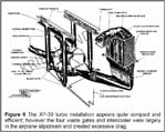
Getting back on topic: one reason the P-39 turbo-charger installation didn't work was because of the bulky external side mounted intercooler and the drag it created. This was attributable to the fact that it didn't use a water cooled intercooler (like the Merlin). Had a water cooled itercooler have been used I assume only an enlarged or deepened radiator would have been needed.

It seems odd that a water cooled engine was compelled to not use a water cooled radiator.
 
I'm told on this forum that radiators have net zero drag? Plus, that XP-39's intercoler was undersized, even for 1150HP?
 
Net zero drag (or better) under the most ideal of circumstances. Realistically most radiator installations will produce some drag most of the time.
 
Than (if the radiator was producing some drag), wasn't that in a function to get more power, and even more power as we fly at high altitude (12,000 and above)?
 
Radiator drag is all over the map. The absolute best, the P-51, may have had zero drag, it may have had positive thrust, it may have had a small amount of drag, anybody that really knows doesn't seem to have talked :)

Using the Meredith to actually get to zero drag or positive was a lot harder than than just saying "we will use the Meredith effect", It is bit like saying "we will just streamline the airplane to get drag co-efficient XX"

And yes the original XP-39 inter-cooler was undersized. And either the engine radiator and oil cooler were undersized or there were severe air flow problems though them as the Prototype had overheating problems on short flights and ground running. Many planes do not like ground running but on the XP-39 they were doing modifications to the ducting before it flew, while it was doing initial flight tests and before handing over to the air corp and as a result of the NACA wind tunnel tests.
 
Net zero drag (or better) under the most ideal of circumstances. Realistically most radiator installations will produce some drag most of the time.

It's basically a ramjet so the faster the airflow (the more 'compression') and also the hotter the heat exchanger then the more thrust can be created. At the speeds of most piston engined aircraft the effect was limited. I wonder if anyone ever tried to add burners after the radiator to augment the thrust?
 
It's basically a ramjet so the faster the airflow (the more 'compression') and also the hotter the heat exchanger then the more thrust can be created. At the speeds of most piston engined aircraft the effect was limited. I wonder if anyone ever tried to add burners after the radiator to augment the thrust?

Not really but some people did try routing the engine exhaust into the radiator exit duct in order to raise the temperature/pressure of the outgoing air.
 
While trying to learn more about the consequences of ram effect to the different planes, something popped out.
The V-1710s with (static) FTH at cca 12,000 ft (found in early P-40s, -39s, 51s) act different with regard to the dynamic (= ram in effect) FTH. The P-40E achieved max speed at 15,000ft, P-51 maxed 13,000+, and P-39D at (surprise, surprise) 12,000 ft.
The later 1710s, with static FTH at cca 15,000ft: P-40N maxed at 16,000, P-51A at 18,000 (static FTH 14,6kft), while P-39Q maxed at mere 13,500 ft (!! - static FTH was at 15,5kft).
We can argue that faster (P-51) can better harvest ram air, but, the P-39 was faster than P-40, yet it cannot excel there...

Another weak point of P-39 ( P-63) - inability to take the advantage of ram effect in a measure other were able to (because intake scoop was both too short and 'in shadow' of the canopy?)?
 
You are on to something Tomo. To get maximum "RAM" the actual intake has to be in a high pressure area and not just facing forward. And it helps if there is enough space for the duct to change shape/direction to convert the speed of the air into pressure.

This is also why the engine maker almost never quotes FTH using "RAM" as it varies from airframe to airframe.
 
Here is a graphic of the P-39 inter-cooler setup. NACA suggested to move it into the radiator ducting to reduce drag.
 

Attachments

  • p39 RADIATOR.jpg
    p39 RADIATOR.jpg
    37.5 KB · Views: 170
  • Turbo install EMAIL- Copy.jpg
    Turbo install EMAIL- Copy.jpg
    128.7 KB · Views: 89
The bottom picture shows an 'ordinary' P-39, not the turbo one.
With intercoolers relocated into (glycol?) radiator's ducting, what should feed the radiator itself?
Were the waste gates inter-cooler really such draggy items, compared perhaps with U/C of P-40, bulges of many Me-109s, added inter-cooler for later Spits etc? IIRC waste gates were faired with sheet metal?
Not to mention that such parts were the ones (among other) that helped creating extra HP, at twice the altitude - eg. nobody was arguing that Spit IX should have it's inter-cooler deleted.
 
Last edited:
Another weak point of P-39 ( P-63) - inability to take the advantage of ram effect in a measure other were able to (because intake scoop was both too short and 'in shadow' of the canopy?)?
Shortround6 said:
You are on to something Tomo. To get maximum "RAM" the actual intake has to be in a high pressure area and not just facing forward. And it helps if there is enough space for the duct to change shape/direction to convert the speed of the air into pressure.
I thought this the first time I saw it. However, I then remembered a program where there was a desire to place the pitot tube inside the engine inlet duct. I thought this was stupid since the inlet often controls inlet pressure, but then ole Bernoulli stuck his nose into the issue. His comment about total pressure being a constant came into play, and since pitot tubes measure total pressure, the placement was just fine. So, unless there is turbulent airflow into the air intake caused by the canopy, and since total pressure is a constant, the higher velocity, lower static pressure, airflow can be easily converted back to the correct parameters by an adequately designed divergent intake.

Space to do this is unknown but Bell surely took the divergent requirement into the original design and it in itself doesn't take much room. The losses incurred in changing the routing to feed the engine is another issue.
 
Last edited:
I'll be the a-hole: Wasn't the whole point behind the P-39 layout that it could mount the T9 cannon? Since that turned out to be not a good weapon, I see no point in trying to make the P-39 work (better) unless you have another (better) weapon that dictates such an arrangement.
 
With belt-fed Hispano in lieu of 37mm, plus 2 x HMGs, the layout looks OK. The firepower comparable to 3-gun Bf-109G-6, La-5, US six-gun fighters, while trumping all the Yaks (not the Yak-9T), 4-gun US fighters, MiG-1/3, Bf-109G-2 (no gondolas) and earlier, many of Japanese fighters, most of the Italian stuff...
Alas, the belt-fed Hispanos were never installed there.
 
I thought this the first time I saw it. However, I then remembered a program where there was a desire to place the pitot tube inside the engine inlet duct. I thought this was stupid since the inlet often controls inlet pressure, but then ole Bernoulli stuck his nose into the issue. His comment about total pressure being a constant came into play, and since pitot tubes measure total pressure, the placement was just fine. So, unless there is turbulent airflow into the air intake caused by the canopy, and since total pressure is a constant, the higher velocity, lower static pressure, airflow can be easily converted back to the correct parameters by an adequately designed divergent intake.

Space to do this is unknown but Bell surely took the divergent requirement into the original design and it in itself doesn't take much room. The losses incurred in changing the routing to feed the engine is another issue.

Air flow can be a funny thing. back in the late 60s General Motors had a number of divisions competing with various "super" cars. Mid sized cars (for the time) with big engines and every one had a "ram" air option of some sort. Pontiac and Buick has two small 'scoops' about half way out the hood. Chevrolet had a rear facing trap door inlet at the base of the windshield. Oldsmobile had two BIG scoops (14 in X 2in If memory serves) under the front bumper. The Oldsmobile set up worked best (biggest scoops and in a high pressure area) the Chevrolet worked next best, the base of the wind shield being a high pressure area. Pontiac setup worked hardly at all while the Buick 'scoops" being very low and in the middle of the hood were actually in a low pressure area and sucked air out from under the hood/intake area. granted these are at much less than aircraft speeds but the air flow along a fuselage is not constant. I would think that putting the intake behind the canopy has got to affect the airflow into it somewhat.

http://www.fiddlersgreen.net/aircraft/Bell-P39-Airacobra/IMAGES/Bell-P-39-Airacobra-Cutaway.jpg
 
With belt-fed Hispano in lieu of 37mm, plus 2 x HMGs, the layout looks OK. The firepower comparable to 3-gun Bf-109G-6, La-5, US six-gun fighters, while trumping all the Yaks (not the Yak-9T), 4-gun US fighters, MiG-1/3, Bf-109G-2 (no gondolas) and earlier, many of Japanese fighters, most of the Italian stuff...
Alas, the belt-fed Hispanos were never installed there.

True, but you can have two Hispanos and 2 HMGs in the wings of any allied single engine fighter, so why bother with such a complex and ultimately troublesome layout. Sure convergence is an issue, but the double cannon should make up for that.
 
Question: If the 37mm cannon was so bad, were the Soviets removing it and/or substituting something else in the space?
 
The bottom picture shows an 'ordinary' P-39, not the turbo one.
With intercoolers relocated into (glycol?) radiator's ducting, what should feed the radiator itself?
Were the waste gates inter-cooler really such draggy items, compared perhaps with U/C of P-40, bulges of many Me-109s, added inter-cooler for later Spits etc? IIRC waste gates were faired with sheet metal?
Not to mention that such parts were the ones (among other) that helped creating extra HP, at twice the altitude - eg. nobody was arguing that Spit IX should have it's inter-cooler deleted.

The NACA report stated that the ducting for cooling the oil and glycol radiator be redesigned to incorporate the intercooler. I put in the P-39 drawing as reference to how the stock version looks.
 
Okay, think I get NACA's idea now :)
An issue of how would anyone succeed to mount intercooler there, is a new ball game.

True, but you can have two Hispanos and 2 HMGs in the wings of any allied single engine fighter, so why bother with such a complex and ultimately troublesome layout. Sure convergence is an issue, but the double cannon should make up for that.

While 2 cannons 4 HMGs as a SE fighter armament do sound like a good idea, the proposal has some shortcomings IMO. Ammo count, for example - we can stick to, say 100-120 shells or 250-300 HMG rounds per barrel. That way our SE fighter lugs around about same armament ammo weight as P-38, P-47, Typhoon, Tempest. Nice if one has at least 2000 HP on board, not that nice if there is only 1200 HP. Or, we can reduce the ammo count to save weight - US pilots would've hated us, and the weight of armament is still there.
We can delete a pair of HMGs, and the armament ammo weight is like at P-51D, Hellcat, Corsair - but our plane still lacks 300-400 HP if we want it to be competitive.
There are other minor things to consider, like need to purchase another 10000 cannons from UK, 3 guns (= cannon + 2 guns) are easier to install maintain than 6, less drag (3 openings less), single gun heater can heat all armament, almost no impact to accuracy if one gun jams, central battery is not susceptible to wing flex, less inertia - better roll...

My proposal cuts weight (P-39 was able to out-climb any contemporary US single-engined fighter anyway), while enabling all 3 guns to be fired simultaneously (similar bullet paths).
 

Users who are viewing this thread

Back