Jumo 004

Ad: This forum contains affiliate links to products on Amazon and eBay. More information in Terms and rules

HoHun

Tech Sergeant
1,759
28
Oct 15, 2006
Hi everyone,

Since there seems to be no thread on the Jumo 004 yet, I thought I'd simply start one with a couple of pictures from the Luftfahrtmuseum Hannover-Laatzen ...

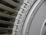
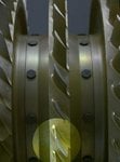
Here is the turbine wheel of the Jumo 004, showing the firtree-style turbine blade attachments.

Regards,

Henning (HoHun)
 

Attachments

  • P1180465_Jumo_004.jpg
    P1180465_Jumo_004.jpg
    66.7 KB · Views: 1,385
Turbine wheel of the Jumo 004
 

Attachments

  • P1180466_Jumo_004.jpg
    P1180466_Jumo_004.jpg
    50.1 KB · Views: 1,158
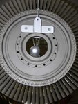
Turbine blades of the Jumo 004
 

Attachments

  • P1180467_Jumo_004.jpg
    P1180467_Jumo_004.jpg
    27.7 KB · Views: 1,023
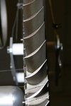
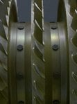
Compressor blades of the Jumo 004
 

Attachments

  • P1180469_Jumo_004.jpg
    P1180469_Jumo_004.jpg
    28 KB · Views: 1,066
Dont know if you seen these Henning. You may find these interesting.
Source of files labeled in pdf files.
 

Attachments

  • Jumo 004B.pdf
    3.2 MB · Views: 1,344
  • Jumo 004-1 Bedienung.pdf
    18.6 MB · Views: 1,268
Hi Micdrow,

>Dont know if you seen these Henning. You may find these interesting.

Thanks a lot! Two or three of these plates are reproduced in von Gersdorff et al., but of course the entire set is much better! :)

For example, I hadn't seen such a detailed diagram of the Jumo 004B instrumentation:

- RPM (controlled automatically according to the position of the thrust lever)
- Exhaust pressure, measured between exhaust and intake
- Fuel injection pressure <- From other sources, this appears to usually have required engine adjustments as the result of acceptance flights.
- Exhaust gas temperature
- Oil pressure

Regards,

Henning (HoHun)
 
Umm is it me
or are those blades at the bottom of the last photo in HoHun's original post at a different angle of attack to the others?
Also, there does not look to be a well defined blade root mounting where the christmas tree joint is and it may simply be the angle of the blade and the camera but it looks odd.
Dragonsinger:confused:
 

Attachments

  • P1180469_Jumo_004.jpg
    P1180469_Jumo_004.jpg
    31.8 KB · Views: 856
Henning,

Judging by the turbine that would be a 004A correct? (004B-1 had solid blades as well, but there were still cooling air chanels delivering air externally to the turbine roots outwar -which consequently resulted in poor cooling toward the blade tips) Though as I havent seen the 004B-1's turbine so I'm not sure.

Here's another good read on the 004:
http://www.enginehistory.org/German/Me-262/Me262_Engine_2.pdf

Came up in the http://www.ww2aircraft.net/forum/aviation/questions-about-me-262-a-15029-6.html thread and I've had it on file for a wile, but haven't read through all of it. It mentions many of the variations in the production 004B, but not which models featured which changes.


So cany anyone give info on the progression of changes throut 004 development, and particularly the differences between the 004B-0,1,2,3,4 and those made on the 004D,E. (and there's also the prototypes to think about; ie 004B-V and A-V)

The only definite differences I know of are that the B-1 had solid (externally air-cooled) turbine bledes (don't know of the B-0) while the B-4 had hollow air-cooled blades. (I don't know about the B-2,3)
And that the 004D had the resonance problems resolved, allowing overrev to 10,000 rpm.

The alloys/metals used seem to vary as well throut development and production. (and not just the hot section) The compressor blades were always stamped aluminum (at least in production models), but the stator blades and intake guide vanse seem to vary considerably both in design and composition. In some cases some of the firs couple stators have with blades made from zinc-plated mild steel (with rearward rows made of aluminum) with others they were all aluminum.

Some versions had some stators with blades constructed with no airfoil shape as well.
 
Hi Koolkitty,

>Judging by the turbine that would be a 004A correct?

Roger, the museum in Laatzen says it's Jumo 004A-022 which made its initial test run in May 1943 and was used for flight testing until January 1944.

Regards,

Henning (HoHun)
 
Umm is it me
or are those blades at the bottom of the last photo in HoHun's original post at a different angle of attack to the others?
Also, there does not look to be a well defined blade root mounting where the christmas tree joint is and it may simply be the angle of the blade and the camera but it looks odd.
Dragonsinger:confused:

I can't explain it in geometric terms, but I'm pretty sure the reason the blades look like they're at a different angles is because you are viewing each blade at a different angle; the blade you pointed out appears to have an increased AOA, whereas if you look two blades up (the blade above the blade that's viewed head-on), you see it appears to have a decreased AOA.

So all of the compressor blades turned in the same direction? I'm used to contra-rotating compressor (and turbine) blades, which I believe is called a two-spool design. The 004 is, obviously, a single-spool design. Not very efficient, as a lot of energy is lost making the air go around in a circle which, in turn, converts the axial velocity of the airstream into rotational velocity, thereby reducing the exit velocity of the airstream from the backside of the compressor section, and reducing the overall thrust. But, I suppose for 1940's technology, it's pretty advanced.
 
No, no, no... That's only the comprossor rotor blading, the stators are stationary and go after each rotor. The stators guide the airflow into the next stage. The stators and intake guide vanes are all stationary, the stators being contained in 2 halves of the casing which surrounds the compressor.


Almost all the sucessful turbojet designs up to the mid 1950's were single-spool.


And the arrangement of a contra-rotating 2-spool design you refer to, with no stators and every other stage turning in the opposite direction doesn't exist on any real world example to my knoledge. (I think there may have been some such designs considered in the WWII timeframe but they were abandoned)

Modern 2-spool engines (and those investigated and tested by the Germans in WWII) have 2 seperate compressor sections (one ahead of the other) running at different speeds, each powered by one or more individual turbine. (various designs rotating in the same or opposite direction, though I believe running in a single direction is more common)
 
Hi Valengo,

>One of my (unfinished) projects in 3D Studio is the Jumo 004, here goes a view.

Wow, that's a very good overview - much better than the 2D sections they had at the museum! :)

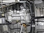
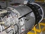
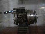
I wish I had taken more photographs ... here are three more, showing the exhaust cone actuator, a view of the actuator and the actuating shaft leading to the exhaust cone, and the Riedel starter engine.

The exhaust tract seems to be different from the one in your 3D model, but maybe that's because the engine I've photographed is a Jumo 004A, not the more typical Jumo 004B ...

Regards,

Henning (HoHun)
 

Attachments

  • P1180471.jpg
    P1180471.jpg
    81.7 KB · Views: 697
Hi again,

Here the exhaust cone actuator and the actuating shaft leading to the exhaust cone, viewing in an aft direction ...

Regards,

Henning (HoHun)
 

Attachments

  • P1180472.jpg
    P1180472.jpg
    72.4 KB · Views: 682
Hi again,

Here the Rieder starter engine ...

Regards,

Henning (HoHun)
 

Attachments

  • P1150416.jpg
    P1150416.jpg
    39 KB · Views: 595

Users who are viewing this thread

Back