Mosquito RS700 Restoration

Ad: This forum contains affiliate links to products on Amazon and eBay. More information in Terms and rules

I may have one. Send me the ID of the hole if you don't mind. Also I have two airworthy prop spinners for a Mosquito,
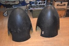
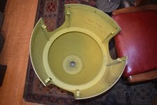
Speak of the devil! The hole cut out is 2-1/4 inches and the mount holes are 2-5/8 inches on the diameter.

We have both our Mosquito spinners so don't need any thanks.
 
Taaadaaa!!!

I did not know, but boy i should have gone to the casino.

If you dont mind Gary to put in some pictures of the spinners....it will be welcomed and perhaps the story how you got them, where the came from....
Hey Snautzer,

I don't have pics of them and they are up at my hangar so I don't have access at the moment. I do have a couple of EC-121 prop spinners here in the shop. Close enough to a Hurricane that some have been used for restorations.
 

Attachments

  • DSC_0001.JPG
    DSC_0001.JPG
    2.4 MB · Views: 6
  • DSC_0002.JPG
    DSC_0002.JPG
    2.1 MB · Views: 6
Gary Cain Gary Cain excuse the perhaps stupid question but what is the difference ? I can understand prop bits, engine bits etc.
Why would it be airworthy?
Instruments are rated as either airworthy, ie you can install it in an aircraft and it is safe to fly, or non airworthy which means it is suitable for display purposes only.

The company that services aircraft clocks has two options, service to airworthy or not.

The price for the work is triple for an airworthy example.

And there is no such thing as a stupid question when it comes to aviation.
 
Last edited:
Instruments are rated as either airworthy, ie you can install it in an aircraft and it is safe to fly, or non airworthy which means it is suitable for display purposes only.

The company that services aircraft clocks has two options, service to airworthy or not.

The price for the work is triple for an airworthy example.

And there is no such thing as a stupid question when it comes to aviation.
For instruments i know. But a prop spinner.
 
Ahh, yes, even prop spinners are going to be rated as airworthy or not. They are inspected for any micro cracks or impending stress failures due to metal fatigue.

If a prop spinner comes apart in flight you are in a world of hurt.

Pretty much EVERY part of an airplane has to be certified as airworthy.
Indeed, but i would have thought it would be part of a bigger cluster of parts. Like hub and prop as 1. Thank you for explaining.
 
I ended up getting an 8 day clock locally but it wasn't a working example, which is fine for the level of restoration that we are trying to achieve. No sooner had I packed this away than an elderly gentleman here in town contacted us by shear coincidence and donated his working 8 day clock along with an RCAF 6AA/378 Tachometer. The latter won't be used in our aircraft but may be offered to another organization that is replicating a Canadian-built Mosquito.

There was an issue with the donated 8 day clock though. The casing had been modified so that the entire mounting flange was removed so that it could be fitted into a Model T Ford for whatever reason. So I toyed with the dead clock to see if I could take it apart easily and take out the movement. Turned out that it was pretty simple - just removed 2 screws on the back, removed the circlip and glass face on the front and the movement came out the front with ease.

20240812_142728.jpg


With my confidence boosted, I set about removing the working movement on the donor clock and, after cleaning the various parts, I installed the working movement into our casing and put the dead one in the modified casing:

20240812_153134.jpg


I would have liked to switch out the winding knobs but there was no way these were coming out easily so I let them be. I might paint the face of the working knob with black enamel to spruce it up.

In other news, the fixed panel onto which the above clock will be mounted will need to be fabricated from scratch. As we have no drawings of the original design, I drew it up on QCAD and printed a front and back image which I taped to the aluminum blank to test the spacing of the various elements and to be sure there were no interferences in this very tight area. Here's the front face:

20240803_101814.jpg


Here's the view from the back of the instrument panel. Note the tight confines. The green plate at the bottom is the top of the rudder pedal doghouse.

20240803_101651.jpg


If the rudder pedals had eyes, this is what they would see when they looked up at the back of the panel. The 3 tubes will eventually connect to the brake air pressure gauge whose cut-out can be seen directly above the tubes. The brake air pressure gauge cut-out will need to be lowered slightly so that the gauge won't foul the doghouse.

20240803_101723.jpg


The holes for the Master Switch will be blanked off as this unit was replaced by the Scintilla unit that contained both the Master Switch and the Mag Switches.

After one or two more needed tweaks, the CAD file will be sent off to a local company that does water-jet cutting and the required holes will be cut into our blank.
 
I ended up getting an 8 day clock locally but it wasn't a working example, which is fine for the level of restoration that we are trying to achieve. No sooner had I packed this away than an elderly gentleman here in town contacted us by shear coincidence and donated his working 8 day clock along with an RCAF 6AA/378 Tachometer. The latter won't be used in our aircraft but may be offered to another organization that is replicating a Canadian-built Mosquito.

There was an issue with the donated 8 day clock though. The casing had been modified so that the entire mounting flange was removed so that it could be fitted into a Model T Ford for whatever reason. So I toyed with the dead clock to see if I could take it apart easily and take out the movement. Turned out that it was pretty simple - just removed 2 screws on the back, removed the circlip and glass face on the front and the movement came out the front with ease.

View attachment 792945

With my confidence boosted, I set about removing the working movement on the donor clock and, after cleaning the various parts, I installed the working movement into our casing and put the dead one in the modified casing:

View attachment 792946

I would have liked to switch out the winding knobs but there was no way these were coming out easily so I let them be. I might paint the face of the working knob with black enamel to spruce it up.

In other news, the fixed panel onto which the above clock will be mounted will need to be fabricated from scratch. As we have no drawings of the original design, I drew it up on QCAD and printed a front and back image which I taped to the aluminum blank to test the spacing of the various elements and to be sure there were no interferences in this very tight area. Here's the front face:

View attachment 792954

Here's the view from the back of the instrument panel. Note the tight confines. The green plate at the bottom is the top of the rudder pedal doghouse.

View attachment 792952

If the rudder pedals had eyes, this is what they would see when they looked up at the back of the panel. The 3 tubes will eventually connect to the brake air pressure gauge whose cut-out can be seen directly above the tubes. The brake air pressure gauge cut-out will need to be lowered slightly so that the gauge won't foul the doghouse.

View attachment 792953

The holes for the Master Switch will be blanked off as this unit was replaced by the Scintilla unit that contained both the Master Switch and the Mag Switches.

After one or two more needed tweaks, the CAD file will be sent off to a local company that does water-jet cutting and the required holes will be cut into our blank.
What do you get when employing kit modellers of some fame in a restoration?

It gets ffing good and correct.

Thats what you get.
 

Users who are viewing this thread

Back