P-51D INSTRUMENT PANEL CRITIQUE

Ad: This forum contains affiliate links to products on Amazon and eBay. More information in Terms and rules

CONNOCHR

Airman
36
2
Dec 19, 2009
New York
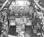
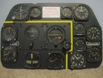
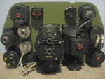
JUST FINISHED A P-51D MUSTANG 1:1 SCALE INSTRUMENT PANEL USING WHATEVER PHOTOS AND INFORMATION I COULD FIND ON THE NET TO MAKE IT AS ORIGINAL AND AUTHENTIC AS POSSIBLE. JUST WANTED TO POST IT SO ANYONE THAT NOTICES AN INACCURACY CAN BE SO KIND AS TO LET ME KNOW SO I CAN ALTER THE PANEL. THANKS EVERYONE.
 

Attachments

  • Img_2120.jpg
    Img_2120.jpg
    87.6 KB · Views: 769
  • Img_2121.jpg
    Img_2121.jpg
    83 KB · Views: 873
Last edited by a moderator:
Mate, looking good, I'm no expert on the P-51 so can't offer detailed comment. You have got the "look at me" lines, so that is great. Good to have yet another 1:1'er here!!

Are Phillips head screws correct? The only reason I ask is that I have them on the Spitfire but they are not correct...should be slot head.

Standard concerns with Radiation and WW2 instruments apply. Personally, I don't like the fact that my Dosimetre is pegged by the compass and TBG at 10 feet. But many say there is not a problem. Not sure if you were aware..that's why I mention it. Do some research if necessary (if not already done) to satisfy yourself. Oh, and pretty much everybody agrees...DON'T open the instruments and inhale Radium Paint dust....nasty stuff.


Re the size..get yourself Infranview (free download, search it on any engine) or something similar. You can then nominate the number of pixels etc that you want.


.
 
Last edited:
Looks good enough to me...to the point where I've saved the pic for reference for models! One thing though, can you type in lower case, it looks like you're shouting!
 
I looked at some of the reference I collected before I decided on a P-47 panel and one from a P-51A (attached below) shows Philip screws. If the P-51A had them it's probably safe to assume that the P-51D had them too. Be careful when you make something to mount it in as mine sort of got out of hand.

P-51A panel.jpg
 
Last edited:
Yes, I was unsure about the phillips head screws but I did the research and found what you just said that they were around during that period and seen on panels in original photos. But however I do see some D panels done in flat headed screws so I went with what I thought would be right, easy fix if turns out to be inaccurate. I also wasn't sure about the nuts used in whether they would have used nylon lock nut, lock washers or a self locking style. I went with what I figured was available at the time the self locking style because I could not find any information or original photos to confirm any other type.
I've been admiring your project which is simply awesome and appears to be an amazing amount of work involved but worth it in the end. I'm resisting the urge to do a full cockpit but you never know.
 
I think the actual screws were brass so as not to interfere with the magnetic field of the compass but I didn't get that carried away – just machine screws from the local hardware store and some black paint.

There are three other guys here building full size cockpits : Gary (Geedee) with a P-51, Darryl (Tony Hill) with a Spitfire, and Tony (Rocketeer) with another Spitfire. Take a look!
 
Looks pretty good to me mate...better than mine by a long shot !. :thumbright: I still have to make the mounting plates for the AH and the sperry and get the yellow line around the basic 6.

Only observation I have is ref the G meter. Not sure when these would have been introduced to the D. Personaly I reckon its one instrument I wouldn't be looking at in a dogfight, prefering to fly eye's out of the cockpit and doing everything possible to stay alive...and win !.

Having said that, one thing I have noticed about '51 instrument panels, is that where you have the G meter, seems to be a 'spare' hole where all sorts of instruments where fiitted. In my panel, I've had a secondary compass and now have an IFF / destruct switch. I've even seen that particluar hole blanked off, so dont lose any sleep.

Now all we've gotta do is to pursuade you to take the next step. Its a big one but well worth it !!!:twisted:
 
Thanks for the input Gary, I've seen what you are doing and that would be a dream come true for me. I have the benefit of a friend with a machine shop for the metal work so maybe in the future I can get some measurements and specs from you to start my own. Regards to your panel you can purchase the directional gyro and gyro horizon mounting plates online for around $22 US and save a bunch of time as I found out after measuring, drawing and cutting on my panel. The yellow line was done by spraying the front of the panel with yellow zinc chromate paint, taping off the line, then spraying the black over. Not sure if that is how North American did it but I found it to be the easiest way to do it. As far as the g-meter, that was one gauge that I wasn't sure about. I've acquired an original technical photo that states either a g-meter or radio compass gauge belongs there for the D model. From what I understand it records the total amount of positive and negative g-forces the plane receives on a flight which can be reset with the knob on the lower left of the gauge afterward. From what I found, this was for the structual integrity of the airframe which had a g-force limit in which it could sustain without bending. If the gauge after a mission recorded a g-force over the limit the aircraft would have to be inspected and measured to make sure the airframe was not damaged, again not sure but this is what I have heard. I also have seen some panel photos with this spot plated off as you said so not sure why that would be. I just went with it as per the tech info. I'll post some photos I have.
 
Here is some of the photos I went by for the panel which shows the accelerometer (g-meter) and what appears to be a radio compass gauge mounted in the lower right port. Not sure when they were taken or in what exact model aircraft but it gives a basic idea of the panel.
 

Attachments

  • P-51CFV.gif
    P-51CFV.gif
    124.4 KB · Views: 2,209
  • P-51D%20Mustang2.jpg
    P-51D%20Mustang2.jpg
    46 KB · Views: 2,662
  • P-51D%20Mustang.jpg
    P-51D%20Mustang.jpg
    62.9 KB · Views: 1,072
Hi mate and thanks for the info. Have not been looking forward too much to making the mounting plates. Did notice a few on that well known internet auction site, but missed the end and lost out.

And yup, its a radio compass I used to have in my panel (its sitting in my shed as I type ) and will probably end up for disposal before much longer.

Hadn't thought about the fatigue checking after each sortie !. And also, one of your shots shows the engine primer unit just above and to the right of the start panel. I've been looking for a decent shot to show where that pump fits as in a lot of modern restorations / airworthy '51's, they just dont appear in any of the pictures.

I reckon you should start off with a 1/4 cockpit...essentially just the panel and a bit of body on either side, a stick top mounted in front and if you can, a hint of windshield. In other words, a bit like T Bolts rig but not including the rudder pedals and all the stuff under the panel. Quite happy to help where possible with stuff and I'm positive the other nutters here who are modelling the full size stuff will 'chip in'. After all, we must be mad to even consider doing what we're trying to do !

And please start a thread when you do !!!!
 
Thanks Gary, If you want I can give you the dimensions of the panels when your ready to do them to save you some figuring time. Yes I will start off small on the cockpit, that would be wise so that I do not get in over my head and thanks for the offer of help. And yes people think we are crazy for doing what we do but those are the people that need to take a little more time to honor the heros that flew these planes in an unimaginable time. Thats why I do it, keep their memories alive for the next generation.
 
Great stuff, and good to know you can help each other out.
Don't know if it'll help, but I have seen it in writing, and also been told by a former P51 pilot (RAF, Mustang III and IV), that the yellow line enclosing the 'Basic Six' was in fact yellow tape, possibly insulating tape. I do remember seeing a photo at one time, where it appeared the line was 'sagging', which presumably was the tape lifting, or peeling, at that particular point.
 
O.k. great information, thank you. That would have been easier to do. That makes sense because I've seen photos of a D panel without the stripe which I guess could have fallen off or been removed if it was tape.
 

Users who are viewing this thread

Back