Which jet was better, the Me 262 or the Gloster Meteor?

Which is better, Me 262 or the Gloster Meteor?


  • Total voters
    131

Ad: This forum contains affiliate links to products on Amazon and eBay. More information in Terms and rules

The following account of an encounter between an Me 262 and a Mosquito is interesting. The Mosquito could apparently out-turn the Schwalbe, at least in this instance...

Luftwaffe: the allied intelligence files - Google Books

Regards,

Magnon

Magnon - a Spad could out turn an Me 262 - so what? think a Spad could survive repeated fast attacks, climb and dive back in? if you don't need to turn and you have a 150kt speed advantage you are an idiot to slow down and engage in the other aircraft comfort zone.
 
There is no reason to speculate that the Me 262 design parameters wandered too much from 8G limit/12G ultimate without factoring Q loads due to drag rise in compressibility..

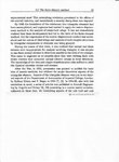
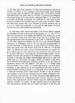
Maybe there is a plausible reason... Some feedback from people who were engaged in analysis of the Me 262 wing using the then new technique of finite elements:
Finite element analysis for ... - Google Books

Quote:
"...The Me 262 had good aerodynamic performance, but suffered many failures due to the poor structural design of its swept back wings; this was a problem which the manufacturers could not overcome at that time..."

The need to carry out stress analysis on swept back wings forced the development of finite element methodology. This didn't really get under way until the digital computer became generally available after the war.

Was the rate of turn of the Me 262 limited by structural considerations, engine operational stability (tendency to flame out), or a combination of both?

I rather suspect the latter...

Regards,

Magnon
 

Attachments

  • Early FEA 001.jpg
    Early FEA 001.jpg
    128.6 KB · Views: 130
  • Early FEA 002.jpg
    Early FEA 002.jpg
    94.8 KB · Views: 130
  • Me262cutaway2.jpg
    Me262cutaway2.jpg
    35.5 KB · Views: 132
Magnon - a Spad could out turn an Me 262 - so what? think a Spad could survive repeated fast attacks, climb and dive back in? if you don't need to turn and you have a 150kt speed advantage you are an idiot to slow down and engage in the other aircraft comfort zone.

The Mosquito was an unarmed reconnaissance aircraft! A good fighter with a speed advantage should have eaten it for breakfast.

The Meteor F3 could get on a Tempest's tail within four turns (see CFE report). The Tempest would eat a Mosquito in a dogfight. The Me 262 could not get onto the Mosquito's tail... Where does that leave the contest between the Meteor and the Me 262?

In US trials of the Me 262 after the War, Chuck Yeager writes:

The Me 163 with its HWK 509C engine was credited with a top speed of 600mph. (The Me 262 with two engines, was clocked at 527 mph)...​

"Breaking the Sound Barrier" Chuck Yeager; Popular Mechanics November 1987.
Page 92

Hans Fey says the bottom limit of acceptance in his trials was 525 mph. That was with the engines new and performing at their best. I've already shown how the thrust dropped off with just 7.5 hours bench testing.

The Meteor F3 had a limit of 493 mph. It could go faster if necessity dictated it in wartime. There was not much in it as far as speed was concerned...

But there were light years in terms of agility and engine reliability. It also had an edge in acceleration, with a 14% higher thrust to weight ratio.

Regards,

Magnon
 
Last edited:
TEC, in the case of this unarmed Mosquito that would indeed have made sense. But the Me 262 pilot used standard Luftwaffe tactics based on optimal use superior speed. Also, higher speed means that the Mossie would have had less time to react. Nevertheless the Mossie pilot was able to turn every time his plane got into firing range of the Me 262.

Fact is that the Mossie was flown by a damn good pilot AND got lucky.
Kris


Another source looks at it from a slightly different perspective:

Here is a case in point, on 25 July ... a 544 squadron Mosquito PR XVI, one of eight sorties the squadron flew that day, MM273 was attacked by an Me262 which made some six firing passes. The Mosquito lost its attacker in 16,000 foot cloud over the Tyrol. It landed at Fermo in Italy. MM273 was lost when it crashed onto the sea off Malta in October 1950.
Re: Me 262 Mythology

You would think that if the Me 262 missed a couple of times, he would wise up and slow down...

Maybe he was feeling sorry for the Mozzy?

Regards,

Magnon
 
The Mosquito was an unarmed reconnaissance aircraft! A good fighter with a speed advantage should have eaten it for breakfast.
WRONG - this has nothing to do with the fighter and everything to do with the pilot and his ability to gain a firing solution during the pursuit. I suggest you research fighter tactics.
The Meteor F3 could get on a Tempest's tail within four turns (see CFE report). The Tempest would eat a Mosquito in a dogfight. The Me 262 could not get onto the Mosquito's tail... Where does that leave the contest between the Meteor and the Me 262?

Again this is meaningless. At what speeds are we talking about in a dogfight between a tempest and a Mosquito or Meteor?!?! And you keep comparing the 262 with the F.3. The F.1 is a fairer comparison.
 
Magnon, you provide great pieces of information. But you puzzle them together in a way they were not meant to.

What were these "many structural failures" of the swept wings? Many Me 262s were lost due to non-combat causes but I can't remember wing failure being among them. And if it was, who is to say it was not because of construction errors, quite common for the last months of German production.

I have also never read that the Me 262 pilot was told to hold back and not push the Me 262 over certain forces. The only thing is that the plans started shaking and snailing at high speeds.

And about the Me 262 vs Mosquito. People often believe that slower bombers/recon aircraft intercepted by a faster and/or nimbler fighter would have no chance. I also tend to think that way. But the figures show that interception does not always lead to destruction. I even think it is more exception than rule.
And in WW2 history there are several aircraft escapes against crazier odds than this Mosquito facing a Me 262.

Kris
 
Maybe there is a plausible reason... Some feedback from people who were engaged in analysis of the Me 262 wing using the then new technique of finite elements:
Finite element analysis for ... - Google Books

Quote:
"...The Me 262 had good aerodynamic performance, but suffered many failures due to the poor structural design of its swept back wings; this was a problem which the manufacturers could not overcome at that time..."

The need to carry out stress analysis on swept back wings forced the development of finite element methodology. This didn't really get under way until the digital computer became generally available after the war.

Was the rate of turn of the Me 262 limited by structural considerations, engine operational stability (tendency to flame out), or a combination of both?

I rather suspect the latter...

Regards,

Magnon


Magnon - why are you dabbling in a field in which you have a.) no theoretical knowledge and b.) try to apply this lack of knowledge to resolve questions you do not understand.

First - look at the cutaway drawing of the Me 262 that you presented. The wing was built up of orthoganally placed structure perpendicular to the spar. In the future, the wings had more sweepback and had a more drastic taper in chord depth in attempts to reduce drag and shift the aerodynamic load distribution inboard to reduce the structural loads on the wing due to both torsion and bending. In such wings the ribs were first designed at an acute angle to the spar. later the airframe design approach varied from orthogaonal to angular depending on other factors.

NASTRAN, curiously developed in part by Larry Ellison IIRC, (computer modelling aspects of relaxation methods between 'elements' to achieve the equillibrium aspired to in your article) was a finite element modelling tool in which Trianglular Plates, rectangular plates, shear panels, beams and Rods were the tools of the structural modeller. This application was the first successful computer model for complex structures and first used in the US Space Program, then shortly afterwards in the Aerospace industry.

IIRC NASTRAN used a combination of Displacement/Node Relaxation methods to iterate to the solution.

The structural failures of the Me 262 were dominantly at >.85 M when the jet was in a dive and in the transonic range which caused the aft movement of the aerodynamic center and a nose down pitch moment requiring enormous stick forces to pull out. In this mode the eppenage was the first failure mode - similar to P-38s and P-47s in a similar dive... and had NOTHING to do with primary failures in the wing spar. The required forces applied to the aft section of the airframe by the elevator to counteract the pitch down moment simple exceeded the design ultimate stress... if the pilot was strong enough.

Similarly, any high speed 'snaking' would introduce asymmetric loads on the eppenage - another hard to predict failure mode in pre-design and very hard to correct in production. That would not have anything to do with the design philosphy regarding Limit and Ultimate Loads - it would simply introduce them in an unexpected (and unanalyzed) flight condition.

Nothing about the article has anything to do with Messerschmidt design philosopy and actually seems to demonstrate some ignorance regarding the actual layout of the Me 262 wing structure.

A competent structures engineer would not model the Me 262 wing with triangular elements if he wished a close approximation of the actuasl to predicted stress levels for the assumed loads. The more difficult problem is the analysis for the applied loads with greater magnitude of spanwise components of lift than a 'straight wing'. This would also result in greater induced drag than predicted by simply applying the equation and using the geometric AR, rather than a 'fudge factor' to compensate for sweep.

Further, the nature of the triangular 'elements' are not clarified. If the model presumed triangular plates and beams as the primary structure - the results would be to create a significantly 'stiifer' (i.e. less displacement) model than real life and yield results that were treading dangerously with respect to underestimating stresses at the joints.

The article didn't specify which side of the "9%" approximation, or I overlooked it ... was it high or low?
 
I am not so sure that such statement has enough data to support the conclusion.. The aspect ratio of the 262 wasn't particularly remarkable for interceptors of the day -

Check out the attached table of aspect ratios... The Me 262 was atypically high.

Magnon - why are you dabbling in a field in which you have a.) no theoretical knowledge and b.) try to apply this lack of knowledge to resolve questions you do not understand.

First - look at the cutaway drawing of the Me 262 that you presented. The wing was built up of orthoganally placed structure perpendicular to the spar. In the future, the wings had more sweepback and had a more drastic taper in chord depth in attempts to reduce drag and shift the aerodynamic load distribution inboard to reduce the structural loads on the wing due to both torsion and bending. In such wings the ribs were first designed at an acute angle to the spar. later the airframe design approach varied from orthogaonal to angular depending on other factors.

A competent structures engineer would not model the Me 262 wing with triangular elements if he wished a close approximation of the actuasl to predicted stress levels for the assumed loads. The more difficult problem is the analysis for the applied loads with greater magnitude of spanwise components of lift than a 'straight wing'. This would also result in greater induced drag than predicted by simply applying the equation and using the geometric AR, rather than a 'fudge factor' to compensate for sweep.

Further, the nature of the triangular 'elements' are not clarified. If the model presumed triangular plates and beams as the primary structure - the results would be to create a significantly 'stiifer' (i.e. less displacement) model than real life and yield results that were treading dangerously with respect to underestimating stresses at the joints.

From what I have read, the Me 262 had up to 3 mm thick skin on the wings. I would have thought it was plausible that a large percentage of the wing strength was invested in this. Without being an expert in finite element analysis, I would also have thought that using triangular elements would be appropriate in analysing this.

Whatever, the bottom line is that all aircraft designers were having trouble with wing structural design at that time (even with straight wings). Torsional deflection was a big problem. Throwing in sweepback into the equation makes design far more complex. It was was just asking for trouble. Then for good measure throw in high aspect ratio combined with low t/c ratio, and the dynamics associated with buffeting in transonic flight regimes...

But then again, you are the expert. More so than the guys who wrote the book, it would appear...

Regards,

Magnon
 

Attachments

  • Aspect Ratio.jpg
    Aspect Ratio.jpg
    56.8 KB · Views: 129
In actuality he probably taught the guys who wrote the book.

Ha Ha... you betya...

The curriculum Vitae of John Argyris
From Wikipedia, the free encyclopedia
John Hadji Argyris (Greek: Ιωάννης Αργύρης; 19 August 1913 in Volos, Greece – 2 April 2004 in Stuttgart) was among the creators of the Finite Element Method (FEM) and lately Professor at the University of Stuttgart and Director of the Institute for Statics and Dynamics of Aerospace Structures. His uncle, Constantin Carathéodory, was a Greek mathematician of the Modern Era. [1]

Curriculum
He was born in Volos, Greece but the family moved to Athens where he was educated in the Classical Gymnasium.

He studied civil engineering for four years in the National Technical University of Athens and then in the Technical University Munich, receiving his Engineering Diploma in 1936. His first job was at the Gollnow company in Stettin, where he was involved among other things in high radio transmitter masts. He was imprisoned by the Nazis for some time but with the help of Admiral Canaris he escaped to Switzerland where he continued his studies in ETH Zurich. In 1943, he joined the research department of the Royal Aeronautical Society in England. Starting from 1949 he was lecturer in aeronautical engineering at the Imperial College London of the University of London, where he assumed a chair in 1955.

In 1959, Argyris was appointed a professor at the Technical University of Stuttgart (today University of Stuttgart) and director of the Institute for Statics and Dynamics of Aerospace Structures. He created the Aeronautical and Astronautical Campus of the University of Stuttgart as focal point for applications of digital computers and electronics.

He died in Stuttgart and is buried in the Sankt Jörgens Cemetery in the city of Varberg, Sweden.

Scientific work
Argyris was involved in and developed to a large extent the Finite Element Method along with Ray W. Clough and Olgierd Zienkiewicz after an early mathematical pre-working of Richard Courant.
He was elected a Fellow of the Royal Society in March 1986.[2]​
Regards,

Magnon
 
Can I ask a question? Why didn't the authors of that aspect ratio graph include th 262 in the quote at the bottom? if it was true?
 
Can I ask a question? Why didn't the authors of that aspect ratio graph include th 262 in the quote at the bottom? if it was true?

Hi Najco

I'm the one who prepared the table. I appended it because it's the only way of including a table in the post.

Regards,

Magnon
 
Ha Ha... you betya...

The curriculum Vitae of John Argyris
From Wikipedia, the free encyclopedia
John Hadji Argyris (Greek: Ιωάννης Αργύρης; 19 August 1913 in Volos, Greece – 2 April 2004 in Stuttgart) was among the creators of the Finite Element Method (FEM) and lately Professor at the University of Stuttgart and Director of the Institute for Statics and Dynamics of Aerospace Structures. His uncle, Constantin Carathéodory, was a Greek mathematician of the Modern Era. [1]

Curriculum
He was born in Volos, Greece but the family moved to Athens where he was educated in the Classical Gymnasium.

He studied civil engineering for four years in the National Technical University of Athens and then in the Technical University Munich, receiving his Engineering Diploma in 1936. His first job was at the Gollnow company in Stettin, where he was involved among other things in high radio transmitter masts. He was imprisoned by the Nazis for some time but with the help of Admiral Canaris he escaped to Switzerland where he continued his studies in ETH Zurich. In 1943, he joined the research department of the Royal Aeronautical Society in England. Starting from 1949 he was lecturer in aeronautical engineering at the Imperial College London of the University of London, where he assumed a chair in 1955.

In 1959, Argyris was appointed a professor at the Technical University of Stuttgart (today University of Stuttgart) and director of the Institute for Statics and Dynamics of Aerospace Structures. He created the Aeronautical and Astronautical Campus of the University of Stuttgart as focal point for applications of digital computers and electronics.

He died in Stuttgart and is buried in the Sankt Jörgens Cemetery in the city of Varberg, Sweden.

Scientific work
Argyris was involved in and developed to a large extent the Finite Element Method along with Ray W. Clough and Olgierd Zienkiewicz after an early mathematical pre-working of Richard Courant.
He was elected a Fellow of the Royal Society in March 1986.[2]​
Regards,

Magnon

Come to think of it, DragonDog, you've questioned the competence of John Argyris. We have his CV. If we had yours, we could compare them and see who was the more credible.

What about it, then?

Regards,

Magnon
 
Ha Ha... you betya...

The curriculum Vitae of John Argyris
From Wikipedia, the free encyclopedia
John Hadji Argyris (Greek: Ιωάννης Αργύρης; 19 August 1913 in Volos, Greece – 2 April 2004 in Stuttgart) was among the creators of the Finite Element Method (FEM) and lately Professor at the University of Stuttgart and Director of the Institute for Statics and Dynamics of Aerospace Structures. His uncle, Constantin Carathéodory, was a Greek mathematician of the Modern Era. [1]

Curriculum
He was born in Volos, Greece but the family moved to Athens where he was educated in the Classical Gymnasium.

He studied civil engineering for four years in the National Technical University of Athens and then in the Technical University Munich, receiving his Engineering Diploma in 1936. His first job was at the Gollnow company in Stettin, where he was involved among other things in high radio transmitter masts. He was imprisoned by the Nazis for some time but with the help of Admiral Canaris he escaped to Switzerland where he continued his studies in ETH Zurich. In 1943, he joined the research department of the Royal Aeronautical Society in England. Starting from 1949 he was lecturer in aeronautical engineering at the Imperial College London of the University of London, where he assumed a chair in 1955.

In 1959, Argyris was appointed a professor at the Technical University of Stuttgart (today University of Stuttgart) and director of the Institute for Statics and Dynamics of Aerospace Structures. He created the Aeronautical and Astronautical Campus of the University of Stuttgart as focal point for applications of digital computers and electronics.

He died in Stuttgart and is buried in the Sankt Jörgens Cemetery in the city of Varberg, Sweden.

Scientific work
Argyris was involved in and developed to a large extent the Finite Element Method along with Ray W. Clough and Olgierd Zienkiewicz after an early mathematical pre-working of Richard Courant.
He was elected a Fellow of the Royal Society in March 1986.[2]​
Regards,

Magnon


Magnon - simply stated you are an ass.

I did not question credentials but offered a professional opinion regarding the inadequacy of using triangular plates to yield close approximations to calculated stresses using conventional structural analysis methods. If Argyris was around to debate this question with me, we could debate intelligently. You on the other hand do not have a clue!

Attached is my resume - Moderators please delete after this idiot gets a chance to read it and post his own resume to confound us with his yet undiscovered brilliance and wherewithal to engage in airframe structures and aerodynamics.

Her 'tis.
 

Attachments

  • Resume_Bill Marshall_Long_lockheed to now.pdf
    154.2 KB · Views: 76
Pretty impressive resume Bill. Congrats on all your achievements!
I am always amazed at the depth of the knowledge of the members on this forum. Thanks to all, I have learned lot.
 
Last edited:
Check out the attached table of aspect ratios...The Me 262 was atypically high.

So what?

From what I have read, the Me 262 had up to 3 mm thick skin on the wings. I would have thought it was plausible that a large percentage of the wing strength was invested in this. Without being an expert in finite element analysis, I would also have thought that using triangular elements would be appropriate in analysing this.

Actually - no and once again you are 'dabbling'. Stop at the point where you say "without being an expert in finite element analysis and ask a simple question. Why are you debating the relative merits, why do make unfounded assumptions and why do you leap to uneducated opinions?

I will guarantee you that the use of .125 skin thickness is the bane of a design engineer's existance because of weight - but if used it was in a region where the transfer of shear from one beam to another resulted in shear web buckling for that area - forcing the greater thickness. This practices frequently found near root chords and also torque boxes.


Whatever, the bottom line is that all aircraft designers were having trouble with wing structural design at that time (even with straight wings). Torsional deflection was a big problem. Throwing in sweepback into the equation makes design far more complex. It was was just asking for trouble. Then for good measure throw in high aspect ratio combined with low t/c ratio, and the dynamics associated with buffeting in transonic flight regimes...

Pray tell, describe the 'troubles' in relation to published airframe limits understood and acknowledged by the designers. Define your phrases 'having trouble with', 'big problem with', 'far more complex', 'just asking for trouble'.

Describe the 'dynamics associated with buffeting' in context of the actual physics and the domains of engineering most likely to be applied to this 'observed result'. Wre we taliking about resonance, periodic vortex shedding, transient loads, flutter, all of the above, more?

Tell us what your qualifications might be to use the terms you have just used?


But then again, you are the expert. More so than the guys who wrote the book, it would appear...

Regards,

Magnon

I am absolutely and unequivocally qualified by education and applied experience to be considered an expert. There are more qualified 'experts' but YOU have no credentials to discern what metrics should apply to make that judgment. I do have such capability and can in fact quickly acknowledge superior knowledge.

Now please produce YOUR CV. We have a quaint expression which loosely translates to "put up or shut up".
 
Last edited:
Pretty impressive resume Bill. Congrats on all your achievements!
I am always amazed at the depth of the knowledge of the members on this forum. Thanks to all, I have learned lot.

Thank you Messy - I have been out of the airframe biz for nearly 40 years so much of the materials science and some of the computer tools have evolved past my experience - but I haven't forgotten any of the requisites for analysis and judgment.

I have a long and early exposure to computer modelling. Even as an undergrad I was a co-op at NASA and helped develop the IBM 620 and 7090 Fortran models for low earth orbit degradation predictions for satellites before getting my degree... it was this fascination which drove me into Information Services as an industry.
 
I am absolutely and unequivocally qualified by education and applied experience to be considered an expert. There are more qualified 'experts' but YOU have no credentials to discern what metrics should apply to make that judgment. I do have such capability and can in fact quickly acknowledge superior knowledge.

Now please produce YOUR CV. We have a quaint expression which loosely translates to "put up or shut up".

BOOM HEADSHOT! :evil4:
 
Magnon - simply stated you are an ass.

I did not question credentials but offered a professional opinion regarding the inadequacy of using triangular plates to yield close approximations to calculated stresses using conventional structural analysis methods. If Argyris was around to debate this question with me, we could debate intelligently. You on the other hand do not have a clue!

Attached is my resume - Moderators please delete after this idiot gets a chance to read it and post his own resume to confound us with his yet undiscovered brilliance and wherewithal to engage in airframe structures and aerodynamics.

Her 'tis.

BOOM HEADSHOT!
 

Users who are viewing this thread

Back