Navigation
Install the app
How to install the app on iOS
Follow along with the video below to see how to install our site as a web app on your home screen.
Note: This feature may not be available in some browsers.
More options
You are using an out of date browser. It may not display this or other websites correctly.
You should upgrade or use an alternative browser.
You should upgrade or use an alternative browser.
1:48 Engine Room #3 Battleship USS New Jersey for Permanent Display on Board.
- Thread starter Builder 2010
- Start date
Ad: This forum contains affiliate links to products on Amazon and eBay. More information in Terms and rules
More options
Who Replied?Night Fighter Nut
Master Sergeant
When I printed something, I washed the parts in a sonic washer filled with isopropyl alcohol approximately 93%. Perhaps that might help with the growth without destroying the part?
Night Fighter Nut
Master Sergeant
Fantastic work by the way. Do you intend to make the rest of the battleship in 48 scale? And will you significant other let you?
Excellent work so far!
- Thread starter
- #145
Builder 2010
Staff Sergeant
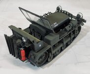
Work continues on two (3) fronts. While designing the next engine room parts, I got a commission to create a 1:32 scale Cletrac M2 Tractor like the one I did a few years ago in 1:48. Two things changed since then. The model is bigger and the printer (and my drawing skills) are better. Taking the original drawings, I upgraded some of fine details that were oversized in the smaller scale Most notable of the are the headlight brush guards. With the new system I was able to draw them so they printed at .010" or a scale 1/4" in 1:1 which is almost the same size as the real ones. They are very fragile and I over-post-hardened them so clipping the tiny supports broke a lot of the cross-bars. I made a bunch. I'm going to adjust post-curing down some since the new printer produces parts that are more solid and less post-hardening is necessary. The model is for a fellow in Minnesota who owns a real one. He's pleased with the results. I made a form-fit foam package that I think will get it to him in one pice.

Printing the decals on white decal paper creates that "Match the Background Color" problem, and even after many, many tries to match the OD color on the computer I still didn't get it right. Under one light the OD clearly is green, and another light it looks redish brown. To make matters worse, I overplayed the horizontal surfaces with a lightened OD to add a little weather fading. This made finding the exact color impossible, since what worked on the vertical surfaces was too dark for the horizontal ones.

Bridal Tulle made the perfect screen wire on the grill guard. I tried to make decals of the instruments, but it was an exercisse in futility.

I was able to refine the drive and idler wheels with photos of the owners real Cletrac, and redrew the track system. i was going to print individual links, but then found out the real links are bolted to a continuous rubber belt. So much for all those armor guys that worry so much about track links. This one is same as all the models we built. I drew in some realistic sag and printed the entire track and wheel system as a single part.

The carton follows practice in packing fine glassware for shipment. With models the key is not let them shift at all in the packing and have nothing touching any delicate parts. This model has a ton of them. The cross-piece just presses down on the hood where there are no protruding details.

Meanwhile, upstairs on my deisgn chair, I was putting the finishing touches on another hugely complex peice of equipment; the steam turbo-generator. There two identical ones side-by-side. I started with that scroll that's spent steam collector that leads directly down to a cylindrical condenser that lies below the TG's frame. It took a lot of tries to get all the plugins and my drawings to work together. It's still not %100, but it's "Close enough for Rock & Roll". That quote comes from my halcyon days in an R&B band at Michigan State University. Whenever we were tuning up, when it was dead on, one of use would say that quote.


There is a maze of piping all over these things. I have to decide what to include or leave out. All the hot parts are covered in a mountain of insulation. I'm presenting the apparatus as no one ever sees it, naked as day it was born. Here's an example:

Printing the decals on white decal paper creates that "Match the Background Color" problem, and even after many, many tries to match the OD color on the computer I still didn't get it right. Under one light the OD clearly is green, and another light it looks redish brown. To make matters worse, I overplayed the horizontal surfaces with a lightened OD to add a little weather fading. This made finding the exact color impossible, since what worked on the vertical surfaces was too dark for the horizontal ones.
Bridal Tulle made the perfect screen wire on the grill guard. I tried to make decals of the instruments, but it was an exercisse in futility.
I was able to refine the drive and idler wheels with photos of the owners real Cletrac, and redrew the track system. i was going to print individual links, but then found out the real links are bolted to a continuous rubber belt. So much for all those armor guys that worry so much about track links. This one is same as all the models we built. I drew in some realistic sag and printed the entire track and wheel system as a single part.
The carton follows practice in packing fine glassware for shipment. With models the key is not let them shift at all in the packing and have nothing touching any delicate parts. This model has a ton of them. The cross-piece just presses down on the hood where there are no protruding details.
Meanwhile, upstairs on my deisgn chair, I was putting the finishing touches on another hugely complex peice of equipment; the steam turbo-generator. There two identical ones side-by-side. I started with that scroll that's spent steam collector that leads directly down to a cylindrical condenser that lies below the TG's frame. It took a lot of tries to get all the plugins and my drawings to work together. It's still not %100, but it's "Close enough for Rock & Roll". That quote comes from my halcyon days in an R&B band at Michigan State University. Whenever we were tuning up, when it was dead on, one of use would say that quote.
There is a maze of piping all over these things. I have to decide what to include or leave out. All the hot parts are covered in a mountain of insulation. I'm presenting the apparatus as no one ever sees it, naked as day it was born. Here's an example:
Attachments
Last edited:
Great work so far!
- Thread starter
- #148
Builder 2010
Staff Sergeant
I think I've finalized the design on the turbogenerators (TGs) and their support systems. It was "fun" figuring out how to run the main piping below the froundation without goig through other pieces of equipment. I swear that a lot of these runs were done on site with the equipement in place. They didn't have 3D CAD programs in 1939 to model it before cutting pipe. I am not including ALL piping, but am putting in enough to tell the story and add interest.
The TGs themselves are on the printer now and will be done later tonight. They're intricate and delicate and I'll be pleased if they come out okay. I will print the support system and the condensers next. Documentation on the condenser foundations are very sketchy (no pun intended), so I basically faked it from the little information I could glean from the photos. Ryan said he couldn't criticize what I drew since he can't tell what's going on there either.
The auxiliary condensers are also an alloy resistent to salt water. They have their own pumps driven electrically and have their own sea chest openings through the ship's bottom. The working floor level is obove the steel foundation supporting the pumps. The guy is actually standing on the hold floor (the 3rd skin of the triple bottom). This image was BEFORE I finalized how the condensers would be fastened to the framing.

You can see more of the piping in these overall views. The room is filling up!
Looking forward: These images show the finalized condenser suspension scheme. Still not sure if it's correct, but until I get better info, it's going to have to do the job.

Looking aft:

The TGs themselves are on the printer now and will be done later tonight. They're intricate and delicate and I'll be pleased if they come out okay. I will print the support system and the condensers next. Documentation on the condenser foundations are very sketchy (no pun intended), so I basically faked it from the little information I could glean from the photos. Ryan said he couldn't criticize what I drew since he can't tell what's going on there either.
The auxiliary condensers are also an alloy resistent to salt water. They have their own pumps driven electrically and have their own sea chest openings through the ship's bottom. The working floor level is obove the steel foundation supporting the pumps. The guy is actually standing on the hold floor (the 3rd skin of the triple bottom). This image was BEFORE I finalized how the condensers would be fastened to the framing.
You can see more of the piping in these overall views. The room is filling up!
Looking forward: These images show the finalized condenser suspension scheme. Still not sure if it's correct, but until I get better info, it's going to have to do the job.
Looking aft:
Vic Balshaw
Major General

- Thread starter
- #151
Builder 2010
Staff Sergeant
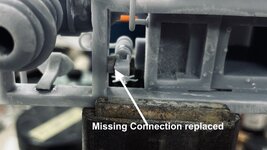
The turbogenerator prints are excellent. I had a minor glitch in the throttle valve and gauge panel not being physically attached to the rest of the model. I glued on one gauge panel and lost the other. I will reprint. Otherwise, I'm very comfortable with this print. Even the control wheel and relief valves rendered well.

Vic Balshaw
Major General
They look great. 
Excellent work so far!
- Thread starter
- #155
Builder 2010
Staff Sergeant
After the pretty decent prints of the turbogenerators, I printed the much larger sub-frame and the support frames for the condensers. I printed the condenser with its support piping, but that was a failure. The drawing was sub-par and the supports weren't strong enough to support the forming part. It created a crevasse that was inoperable. I bit the bullet and completely redrew the shell making sure it was fully hollow with perfecly formed walls in and out. It will be printed tomorrow.


I decided to print the new condenser barrels separately from its attached pumps and piping to simplify positioning on the printer and insure sucess.
The sub-frame needed some clean up and minor Bondic work on one corner. It also had a complete, non-complicated fracture in one of the side beams. When resin changes state from liquid to solid it creates internal stresses. Sometimes it leads to warping—although in this printer warpage has not been a problem—and, as in this case, breakage. I used Bondic to repair it, and after some mild sanding, the break is invisible. It would be invisible anyway since it will be very difficult to view.
I made the mounting holes for the legs as part of the drawing. There were some weird situations, which occurs in SketchUp, where when you intersect faces from one object to another, the lines don't create a new surface that can be extruded by failing to create an actual surface. For these instances I drilled a small hole to guide a drill in a post-op.
Here is the repaired corner.

The top view of the sub-frame after cleaning.

And the bottom.

I positioned the TGs on the frame for this image.

Today, the leg and condenser mounting system was printed successfully. As will all printed objects, if you want a shaft and hole to fit be prepared to enlarge the hole or reduce the o.d. of the shaft. This is because the two diameters made from the same drawing would be a press, zero-clearance fit. And, due to the nature of resin printing, the shafts are a couple of thousandths (15 microns) larger and the holes are correspondingly smaller. I took one of the legs that was to fit in the holes and measured it with a drill gauge. A nice clearance was a #18 drill. I opened all the holes to this diamter.
Here's the sub-frame on the legs. One of the legs wasn't in full contact with the cross-beam on the drawing and printed as a separate part. i put it on after fitting the pieces into the sub-frame to insure that its alignment was correct. I fastened it with Bondic AND CA. You will notice that the arm on the relief valve is missing on the TG in the foreground. It wasn't the only thing wrong with these prints. The steam throttle body wasn't attached to anything being held just by the two pipes, and the gauge panel suffered from the same malady due to forgetting to draw the attachment. I printed a spacer set for the throttles and new gauge panels. I attempted to glue all this together with CA. It didn't look very good. Then I broke off that little arm. I really liked that detail since it printed so beautifully. The result: I reprinted both of them. Once I know something this important isn't right and I have the time and resin to do it over, I will do it over. Visitors to the ship have no idea that these machines are suspended on legs so far above the hold. Seeing this model, they will understand it.

Looking up into the supports you see the nice perforated cross-piece. This stuff was almost impossible to photograph in the 1:1 ship, that no one, and I mean no one will be able to discerne that this is either realistic or not. Modeler's license.

I'm working on the evaporators. These are only located in ER #3. There are three heat vessels. The left end takes in seawater, boils it. It's steam goes to the middle where is condensed with some condensate being removed and the remainder reboiled again with its steam going to the last vessel and it happens again. The output of the middle vessel produces potible water for crew, the 3rd produces feedwater for the boilers. In other words, the boilers get better water than the crew. I don't have detailed drawings of these, and my photos only show the front faces, I don't know where the piping goes when leaving the evaporators. I do know that the feedwater is stored in tankage in the walls of the ship immediately behind these units. Remmber, there are 20 feet of voids, tanks and armor between the engine room's walls and the ship's exterior.

Lastly, I've redrawn the growing overall project image with the new acrylic bulkheads. This is a better solution that the cutaway slivers that I was originally thinking about.

I've completed the print files for the floor grating. I still don't know how many gratings I will install. They form all the working decks that separate the levels within the engine rooms. Install too many and views will be blocked, but none will give the illusion that people work on montrous machines that tower over their heads. They are supported by angle-iron frames that are very frail in 1:48 scale. I suppose I could print the grating with its supporting angle iron framing. I will see if I can old-school cobble the frames out of styrene shapes. If it's too ridiculous I will use the printer.
I looking at that picture, I'm thinking the bulkheads could actually form the display case… Hmmm. The shafts would protrude, but that may add interest. Otherwise, you'll have acrylic walls surrounded by more acrylic. We'lll see. Posting helps me think...
I decided to print the new condenser barrels separately from its attached pumps and piping to simplify positioning on the printer and insure sucess.
The sub-frame needed some clean up and minor Bondic work on one corner. It also had a complete, non-complicated fracture in one of the side beams. When resin changes state from liquid to solid it creates internal stresses. Sometimes it leads to warping—although in this printer warpage has not been a problem—and, as in this case, breakage. I used Bondic to repair it, and after some mild sanding, the break is invisible. It would be invisible anyway since it will be very difficult to view.
I made the mounting holes for the legs as part of the drawing. There were some weird situations, which occurs in SketchUp, where when you intersect faces from one object to another, the lines don't create a new surface that can be extruded by failing to create an actual surface. For these instances I drilled a small hole to guide a drill in a post-op.
Here is the repaired corner.
The top view of the sub-frame after cleaning.
And the bottom.
I positioned the TGs on the frame for this image.
Today, the leg and condenser mounting system was printed successfully. As will all printed objects, if you want a shaft and hole to fit be prepared to enlarge the hole or reduce the o.d. of the shaft. This is because the two diameters made from the same drawing would be a press, zero-clearance fit. And, due to the nature of resin printing, the shafts are a couple of thousandths (15 microns) larger and the holes are correspondingly smaller. I took one of the legs that was to fit in the holes and measured it with a drill gauge. A nice clearance was a #18 drill. I opened all the holes to this diamter.
Here's the sub-frame on the legs. One of the legs wasn't in full contact with the cross-beam on the drawing and printed as a separate part. i put it on after fitting the pieces into the sub-frame to insure that its alignment was correct. I fastened it with Bondic AND CA. You will notice that the arm on the relief valve is missing on the TG in the foreground. It wasn't the only thing wrong with these prints. The steam throttle body wasn't attached to anything being held just by the two pipes, and the gauge panel suffered from the same malady due to forgetting to draw the attachment. I printed a spacer set for the throttles and new gauge panels. I attempted to glue all this together with CA. It didn't look very good. Then I broke off that little arm. I really liked that detail since it printed so beautifully. The result: I reprinted both of them. Once I know something this important isn't right and I have the time and resin to do it over, I will do it over. Visitors to the ship have no idea that these machines are suspended on legs so far above the hold. Seeing this model, they will understand it.
Looking up into the supports you see the nice perforated cross-piece. This stuff was almost impossible to photograph in the 1:1 ship, that no one, and I mean no one will be able to discerne that this is either realistic or not. Modeler's license.
I'm working on the evaporators. These are only located in ER #3. There are three heat vessels. The left end takes in seawater, boils it. It's steam goes to the middle where is condensed with some condensate being removed and the remainder reboiled again with its steam going to the last vessel and it happens again. The output of the middle vessel produces potible water for crew, the 3rd produces feedwater for the boilers. In other words, the boilers get better water than the crew. I don't have detailed drawings of these, and my photos only show the front faces, I don't know where the piping goes when leaving the evaporators. I do know that the feedwater is stored in tankage in the walls of the ship immediately behind these units. Remmber, there are 20 feet of voids, tanks and armor between the engine room's walls and the ship's exterior.
Lastly, I've redrawn the growing overall project image with the new acrylic bulkheads. This is a better solution that the cutaway slivers that I was originally thinking about.
I've completed the print files for the floor grating. I still don't know how many gratings I will install. They form all the working decks that separate the levels within the engine rooms. Install too many and views will be blocked, but none will give the illusion that people work on montrous machines that tower over their heads. They are supported by angle-iron frames that are very frail in 1:48 scale. I suppose I could print the grating with its supporting angle iron framing. I will see if I can old-school cobble the frames out of styrene shapes. If it's too ridiculous I will use the printer.
I looking at that picture, I'm thinking the bulkheads could actually form the display case… Hmmm. The shafts would protrude, but that may add interest. Otherwise, you'll have acrylic walls surrounded by more acrylic. We'lll see. Posting helps me think...
Attachments
Vic Balshaw
Major General
I'm still gobsmacked.
Nice work so far!
- Thread starter
- #159
Builder 2010
Staff Sergeant
Well… printing the condensers has been a bit of a challenge. Yesterday's print failed at 47%. We were out to dinner when the printer stopped. I rebooted it and it asked if I wanted to continue the paused print. I said "Yes", it stated printing, but when I went down to see it, the print looked like this:

And PAF film at the resin vat's bottom.

After popping the cured resin off the film, and futher inspection, it looked like a good time to change it out. I was at 47,000 layers when the job started. Changing out the film is not hard, but it is a bit time consuming. There are two layers of screws. First to fasten the entire frame into the vat body, and then 28 smaller screws to fasten the two halves of the sealing frame together. This view shows the new film in place and the film frame fastened into the vat frame.

Here's the screws removed to release the old film.

The new film seemed to work and I finally got a perfect print of the TG condensers. It's the weekend so I won't be in the shop. I will clean these up on Monday. Here they are in the draining fixture. By letting the excess resin simply drain off greatly reduces the resin loading in the alcohol wash and saves expensive resin.

I also got the sub-frame and evaporators finish designed and built the first ladder on the specifics of this particular ladder based on the ladder detail drawings I have. They're all different and all identified. I put in a smattering of floor gratings. I'm going to print a bunch of these so I'll be able to put them where they do the most good. The evaporators are also supported on columns just as the turbogerators are.


And PAF film at the resin vat's bottom.
After popping the cured resin off the film, and futher inspection, it looked like a good time to change it out. I was at 47,000 layers when the job started. Changing out the film is not hard, but it is a bit time consuming. There are two layers of screws. First to fasten the entire frame into the vat body, and then 28 smaller screws to fasten the two halves of the sealing frame together. This view shows the new film in place and the film frame fastened into the vat frame.
Here's the screws removed to release the old film.
The new film seemed to work and I finally got a perfect print of the TG condensers. It's the weekend so I won't be in the shop. I will clean these up on Monday. Here they are in the draining fixture. By letting the excess resin simply drain off greatly reduces the resin loading in the alcohol wash and saves expensive resin.
I also got the sub-frame and evaporators finish designed and built the first ladder on the specifics of this particular ladder based on the ladder detail drawings I have. They're all different and all identified. I put in a smattering of floor gratings. I'm going to print a bunch of these so I'll be able to put them where they do the most good. The evaporators are also supported on columns just as the turbogerators are.
Last edited:
Users who are viewing this thread
Total: 1 (members: 0, guests: 1)