Thanks all!
Today I'm started making some strategic inroads into assembly. Not actual assembly, but more like "assembly prep." What follows is a bit arcane so please follow closely.
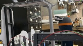
All that's left to paint is the fore and aft "swiss cheese" bulkheads. Before painting I had to install the inside support beams that would hold up the aft end of the entry level floor. To measure the placement for these pieces I had to have the entry floor epoxied to the main support column which, in my rendition, is what's holding up the fore end of the entry floor structure. In the real ship, the entry floor is supported by the entire third deck's flooring system, which is missing on my model. After epoxying these two sub-assemblies together, I had to place all the necessary equipment on the hold floor so I would get an accurate placement. While doing that I attempted to fit the large crew floor piece that I made yesterday, and found that it interfered with the starboard main reduction gear angle brackets. I made quick work of creating relief cuts so it would snuggle to the correct spot.


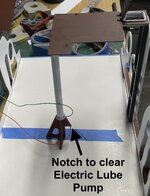
I suspected I would find other interference areas and didn't have to wait long. When I put the central column into place next to the MRG's frame, the column's aft triangular bottom brace brace crashed into the electric lube oil pumps foundation. In this case, it was easier to hack away at the column base than to surgically alter the pump since it was part of a larger structure and would have been more troublesome to modify.
Before epoxying the column to the entry floor system I had to be darn sure that I was putting it in the correct location. This took some trial and error get the positioning right. I'm using 5 minute epoxy and glad I did. I had to hand-hold the two parts in alignment until it set up enough to sefl-support when placed on the table top to finish cure. The relief cut is pretty obvious.
After I was able to locate and mark the height and lateral location of the support frames, I cut them from some scrap Plastruct I-beam I had left over from a previous project from years ago. I cut some cross pieces that needed to be notched so they nested into the verticals. I glued them together with solvent cement. Plastruct parts are ABS plastic. I then positioned the frame onto the bulkhead to recheck its positioning.
The trial fit has the floor at the very top of the bulkhead wall, which is actually correct.
I got worried that it may impinge with the aft MRG frame and did a quick check and found that there did clear, albeit closely. When the gear box is place there still may be some interference, but I make it work.
In this case I used rubber-infused CA to glue the frame to the styrene wall. Again I needed to make sure that the hold floor would be able to slip underneath the supports before gluing. I was able to slipit underneath. With that last check, I was able to glue it in place and clamp until cured. This newer CA product needs 15 seconds to cure so I was able to adjust plumb.
To do the bulkhead painting I needed to mask all the oxide red parts including the hold floors. This morning I awoke realizing that with the floors not being glued in yet, I could easily substitute carboard for the real floors, and do the painting without worrying about them. I still have to mask the exterior areas, which I had already started. tomorrow, I should finish masking, paint the bulkheads and we'll be ready to start fastening things to the real floors.
I was doing finish painting on the low pressure turbine, and knew all along that there was something funny about the fit, but left it go until later. Today was that "later" time, and I needed to do some router surgery. Don't know why the rotor fit into the lower half, but the upper quadrant wouldn't get close to fitting. I had to remove a lot of stock from the bearing portion that separates the low pressure and astern turbine wheels. Once I did the surgery, the parts fit and can be permanently assembled.
Onwards and upwards!