Great work so far!
Navigation
Install the app
How to install the app on iOS
Follow along with the video below to see how to install our site as a web app on your home screen.
Note: This feature may not be available in some browsers.
More options
You are using an out of date browser. It may not display this or other websites correctly.
You should upgrade or use an alternative browser.
You should upgrade or use an alternative browser.
1:48 Engine Room #3 Battleship USS New Jersey for Permanent Display on Board.
- Thread starter Builder 2010
- Start date
Ad: This forum contains affiliate links to products on Amazon and eBay. More information in Terms and rules
More options
Who Replied?- Thread starter
- #322
Builder 2010
Staff Sergeant
I deleted a duplicate post from yesterday
- Thread starter
- #323
Builder 2010
Staff Sergeant
Painted pipes today, and continued picking out the small details. Got the third floor system printed and post-cured, and redrew the first one and it's going to be printed tomorrow.

As I noted on my last post, the supports had some wrap-around which pulled one of the legs and cross-bracing off in the cleaning process. I've often said that removing supports is the #1 failure mode of 3D prints, especially when they're as complex as some of these are. Since I was scraping the first one printed, I was able to scavenge some pieces to graft them to this, otherwise perfect, floor system.

More to come tomorrow. Please ignore the slight size difference of the front portion between the two sides. When installed, it will not be noticeable and I didn't want to reprint just to fix that.
As I noted on my last post, the supports had some wrap-around which pulled one of the legs and cross-bracing off in the cleaning process. I've often said that removing supports is the #1 failure mode of 3D prints, especially when they're as complex as some of these are. Since I was scraping the first one printed, I was able to scavenge some pieces to graft them to this, otherwise perfect, floor system.
More to come tomorrow. Please ignore the slight size difference of the front portion between the two sides. When installed, it will not be noticeable and I didn't want to reprint just to fix that.
Excellent work so far!
- Thread starter
- #326
Builder 2010
Staff Sergeant
Painting continues and is almost done. If I get a good, long session tomorrow I could get it all done. We had a break in all the thunder storms and I got the base red done on all the decks and deck supports. I have a couple more red parts to paint, but probably won't have to do it outside. On the right is the newly-printed main floor replacement.

I detail painted the HP throttles. There's some painting to do on the upper quandrant of the LP turbine, a few tiny details on the turbo-generators and painting the replacement lube purifier. There's some touch up work on the various air ejectors, but that's all minor stuff. Once all this is done, the last painting is the white bulkheads. When that is done equipment placement will begin sometimg this week. The throttle springs are molotow chrome base with Tamiya clear blue overcoat.

All the railing I have to solder are 32" high. Instead of soldering a retainer at the bottom to hold the correct depth, I drew and 3D printed a bunch of scale 32" spacers that I will use to set all the railings at the same height during gluing. The little frame next to my power sander is the last catwalk support for the very narrow grated walkway between the HP and LP turbines. I think it's the last support piece I need to design and print.

I detail painted the HP throttles. There's some painting to do on the upper quandrant of the LP turbine, a few tiny details on the turbo-generators and painting the replacement lube purifier. There's some touch up work on the various air ejectors, but that's all minor stuff. Once all this is done, the last painting is the white bulkheads. When that is done equipment placement will begin sometimg this week. The throttle springs are molotow chrome base with Tamiya clear blue overcoat.
All the railing I have to solder are 32" high. Instead of soldering a retainer at the bottom to hold the correct depth, I drew and 3D printed a bunch of scale 32" spacers that I will use to set all the railings at the same height during gluing. The little frame next to my power sander is the last catwalk support for the very narrow grated walkway between the HP and LP turbines. I think it's the last support piece I need to design and print.
Great work so far!
- Thread starter
- #329
Builder 2010
Staff Sergeant
Detail painting continues...
The turbo-generators are for all intents and purposes are finished painted. There may be a touchup or two I have to do, but they're done. I had to replace one of those vertical guard poles with wire when one broke off at some point. 600 pound steam lines connect to those two valve bodies. The "copper" color was created by a chrome cylinder base covered with a mix of Tamiya Clear Red and Clear Yellow in an imprecise ratio.

The main and aux air ejectors are also just about finish painted. I hate brush painting white paint!!! Valve handles need painting/replacing where missing.

And, except for some very minor touchup, the main gauge panel is done. Wish I could have done decals for the gauge faces, but inkjet decals just don't work in this size.

Here's the composite photo I used to paint it.

The turbo-generators are for all intents and purposes are finished painted. There may be a touchup or two I have to do, but they're done. I had to replace one of those vertical guard poles with wire when one broke off at some point. 600 pound steam lines connect to those two valve bodies. The "copper" color was created by a chrome cylinder base covered with a mix of Tamiya Clear Red and Clear Yellow in an imprecise ratio.
The main and aux air ejectors are also just about finish painted. I hate brush painting white paint!!! Valve handles need painting/replacing where missing.
And, except for some very minor touchup, the main gauge panel is done. Wish I could have done decals for the gauge faces, but inkjet decals just don't work in this size.
Here's the composite photo I used to paint it.
Vic Balshaw
Major General
This is some real nice work. 
- Thread starter
- #332
Builder 2010
Staff Sergeant
Thanks all!
Today I'm started making some strategic inroads into assembly. Not actual assembly, but more like "assembly prep." What follows is a bit arcane so please follow closely.
All that's left to paint is the fore and aft "swiss cheese" bulkheads. Before painting I had to install the inside support beams that would hold up the aft end of the entry level floor. To measure the placement for these pieces I had to have the entry floor epoxied to the main support column which, in my rendition, is what's holding up the fore end of the entry floor structure. In the real ship, the entry floor is supported by the entire third deck's flooring system, which is missing on my model. After epoxying these two sub-assemblies together, I had to place all the necessary equipment on the hold floor so I would get an accurate placement. While doing that I attempted to fit the large crew floor piece that I made yesterday, and found that it interfered with the starboard main reduction gear angle brackets. I made quick work of creating relief cuts so it would snuggle to the correct spot.


I suspected I would find other interference areas and didn't have to wait long. When I put the central column into place next to the MRG's frame, the column's aft triangular bottom brace brace crashed into the electric lube oil pumps foundation. In this case, it was easier to hack away at the column base than to surgically alter the pump since it was part of a larger structure and would have been more troublesome to modify.
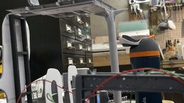
Before epoxying the column to the entry floor system I had to be darn sure that I was putting it in the correct location. This took some trial and error get the positioning right. I'm using 5 minute epoxy and glad I did. I had to hand-hold the two parts in alignment until it set up enough to sefl-support when placed on the table top to finish cure. The relief cut is pretty obvious.

After I was able to locate and mark the height and lateral location of the support frames, I cut them from some scrap Plastruct I-beam I had left over from a previous project from years ago. I cut some cross pieces that needed to be notched so they nested into the verticals. I glued them together with solvent cement. Plastruct parts are ABS plastic. I then positioned the frame onto the bulkhead to recheck its positioning.

The trial fit has the floor at the very top of the bulkhead wall, which is actually correct.

I got worried that it may impinge with the aft MRG frame and did a quick check and found that there did clear, albeit closely. When the gear box is place there still may be some interference, but I make it work.

In this case I used rubber-infused CA to glue the frame to the styrene wall. Again I needed to make sure that the hold floor would be able to slip underneath the supports before gluing. I was able to slipit underneath. With that last check, I was able to glue it in place and clamp until cured. This newer CA product needs 15 seconds to cure so I was able to adjust plumb.

To do the bulkhead painting I needed to mask all the oxide red parts including the hold floors. This morning I awoke realizing that with the floors not being glued in yet, I could easily substitute carboard for the real floors, and do the painting without worrying about them. I still have to mask the exterior areas, which I had already started. tomorrow, I should finish masking, paint the bulkheads and we'll be ready to start fastening things to the real floors.

I was doing finish painting on the low pressure turbine, and knew all along that there was something funny about the fit, but left it go until later. Today was that "later" time, and I needed to do some router surgery. Don't know why the rotor fit into the lower half, but the upper quadrant wouldn't get close to fitting. I had to remove a lot of stock from the bearing portion that separates the low pressure and astern turbine wheels. Once I did the surgery, the parts fit and can be permanently assembled.


Onwards and upwards!
Today I'm started making some strategic inroads into assembly. Not actual assembly, but more like "assembly prep." What follows is a bit arcane so please follow closely.
All that's left to paint is the fore and aft "swiss cheese" bulkheads. Before painting I had to install the inside support beams that would hold up the aft end of the entry level floor. To measure the placement for these pieces I had to have the entry floor epoxied to the main support column which, in my rendition, is what's holding up the fore end of the entry floor structure. In the real ship, the entry floor is supported by the entire third deck's flooring system, which is missing on my model. After epoxying these two sub-assemblies together, I had to place all the necessary equipment on the hold floor so I would get an accurate placement. While doing that I attempted to fit the large crew floor piece that I made yesterday, and found that it interfered with the starboard main reduction gear angle brackets. I made quick work of creating relief cuts so it would snuggle to the correct spot.
I suspected I would find other interference areas and didn't have to wait long. When I put the central column into place next to the MRG's frame, the column's aft triangular bottom brace brace crashed into the electric lube oil pumps foundation. In this case, it was easier to hack away at the column base than to surgically alter the pump since it was part of a larger structure and would have been more troublesome to modify.
Before epoxying the column to the entry floor system I had to be darn sure that I was putting it in the correct location. This took some trial and error get the positioning right. I'm using 5 minute epoxy and glad I did. I had to hand-hold the two parts in alignment until it set up enough to sefl-support when placed on the table top to finish cure. The relief cut is pretty obvious.
After I was able to locate and mark the height and lateral location of the support frames, I cut them from some scrap Plastruct I-beam I had left over from a previous project from years ago. I cut some cross pieces that needed to be notched so they nested into the verticals. I glued them together with solvent cement. Plastruct parts are ABS plastic. I then positioned the frame onto the bulkhead to recheck its positioning.
The trial fit has the floor at the very top of the bulkhead wall, which is actually correct.
I got worried that it may impinge with the aft MRG frame and did a quick check and found that there did clear, albeit closely. When the gear box is place there still may be some interference, but I make it work.
In this case I used rubber-infused CA to glue the frame to the styrene wall. Again I needed to make sure that the hold floor would be able to slip underneath the supports before gluing. I was able to slipit underneath. With that last check, I was able to glue it in place and clamp until cured. This newer CA product needs 15 seconds to cure so I was able to adjust plumb.
To do the bulkhead painting I needed to mask all the oxide red parts including the hold floors. This morning I awoke realizing that with the floors not being glued in yet, I could easily substitute carboard for the real floors, and do the painting without worrying about them. I still have to mask the exterior areas, which I had already started. tomorrow, I should finish masking, paint the bulkheads and we'll be ready to start fastening things to the real floors.
I was doing finish painting on the low pressure turbine, and knew all along that there was something funny about the fit, but left it go until later. Today was that "later" time, and I needed to do some router surgery. Don't know why the rotor fit into the lower half, but the upper quadrant wouldn't get close to fitting. I had to remove a lot of stock from the bearing portion that separates the low pressure and astern turbine wheels. Once I did the surgery, the parts fit and can be permanently assembled.
Onwards and upwards!
Attachments
Vic Balshaw
Major General

Excellent work so far!
- Thread starter
- #336
Builder 2010
Staff Sergeant
Thanks as always.
Finished masking the base, took it outside and sprayed it with Tamiya White Primer. When it was dry (it drys fast) I brougt it inside and sprayed a second coat of Tamiya Gloss White. After pulling the tape I found some erros and areas where overspray got behind the mask and touched up with Oxide Red and the white where necessary.


I then noted the locations of all the inner structure on the card stock that I used to mask the inside and made a grid that I could use to locate all the penetrations for the LED wiring that needed to pass through the ship's base and through the wood base.

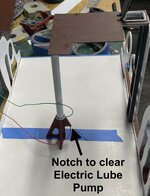
I placed the critical pieces on the card stock and noted where the holes should go so they would clear any of the internal structure. I found, to my annoyance, that I still missed the correct openings on the integrated floor prints. I'm not going to reprint. I will repair them so they'll work. I still have to pay attention where the base "concrete" blocks will go. I can drill though them if they're in the way, but would choose not to. I have to remove a square notch in the aft, starboard side of the electrical mezannine frames to accept the escape trunk. I already made accommodations for the trunk on the stepped-down walkway frame.
The image shows one location: the leads coming from the evaporator frame. It was gratifying that the main steam pipe wrapped around the central column as I designed and the entry floor was still able to align well with the wall.

Happy Friday. Work resumes on Monday.
Finished masking the base, took it outside and sprayed it with Tamiya White Primer. When it was dry (it drys fast) I brougt it inside and sprayed a second coat of Tamiya Gloss White. After pulling the tape I found some erros and areas where overspray got behind the mask and touched up with Oxide Red and the white where necessary.
I then noted the locations of all the inner structure on the card stock that I used to mask the inside and made a grid that I could use to locate all the penetrations for the LED wiring that needed to pass through the ship's base and through the wood base.
I placed the critical pieces on the card stock and noted where the holes should go so they would clear any of the internal structure. I found, to my annoyance, that I still missed the correct openings on the integrated floor prints. I'm not going to reprint. I will repair them so they'll work. I still have to pay attention where the base "concrete" blocks will go. I can drill though them if they're in the way, but would choose not to. I have to remove a square notch in the aft, starboard side of the electrical mezannine frames to accept the escape trunk. I already made accommodations for the trunk on the stepped-down walkway frame.
The image shows one location: the leads coming from the evaporator frame. It was gratifying that the main steam pipe wrapped around the central column as I designed and the entry floor was still able to align well with the wall.
Happy Friday. Work resumes on Monday.
Vic Balshaw
Major General
Looking good.
Great work so far!
T Bolt
Colonel
Users who are viewing this thread
Total: 1 (members: 0, guests: 1)