Excellent work so far!
Navigation
Install the app
How to install the app on iOS
Follow along with the video below to see how to install our site as a web app on your home screen.
Note: This feature may not be available in some browsers.
More options
You are using an out of date browser. It may not display this or other websites correctly.
You should upgrade or use an alternative browser.
You should upgrade or use an alternative browser.
1:48 Engine Room #3 Battleship USS New Jersey for Permanent Display on Board. (1 Viewer)
- Thread starter Builder 2010
- Start date
Ad: This forum contains affiliate links to products on Amazon and eBay. More information in Terms and rules
More options
Who Replied?- Thread starter
- #482
Builder 2010
Staff Sergeant
Back from France. Saw a lot, did a lot, tasted a lot of wine in Chablis, Beaune, Dijon and other places in Burgundy. Spent and equal amount of time in Paris seeing things that I hadn't seen before. While I have been in Paris at least 6 times, there's still more to see. One of the most memorable was seeing the newly finished Notre Dame. It's looking as good as ever in its 800 year history. We walked up to five miles a day and my 80 year old body feels it. My wife and I both returned with colds, which seems par for the course in air travel these days. All I did with the model is reprint the 10 step ladders today. I was printing the new 4 and 10 step ladders the day we left, but the thumb drive ceased feeding data to the printer leaving the 10 step ladders half printed. I get them tomorrow. If I still feel like I do today, I will not be in the shop. More to come...
Vic Balshaw
Major General
Glad you had a great time in France, it's a food and wine paradise and if you can find the time to see the sights, that's a bonus. One of my best ever meals was in the Latin Quarter a simple beautifully cooked steak and fresh buttered green beans, it was perfect after a day walking the city.
- Thread starter
- #484
Builder 2010
Staff Sergeant
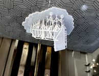
My cold morphed into a normal cold on its way out and my energy level was high enough to get to work on the beast. And, believe it or not, there is only a single part that needed design and printing to finish it off on Monday. The missing part is this ladder that goes from the mid-level to the lower electric mezzanine. Not only hadn't I printed it (looks like 7 rungs), I really didn't plan well for it's installation as you can by the master drawing. The drawing shows a ladder that's interfering with the framing next to, and there's nothing supporting the free end.

It's going to go here.

To facilitate installatin, I drew and printed the ladder with a bit of framing and grating. It printed right at the end of the session and the print looks successful. I printed only one as I wasn't sure how successful it would be. With its success, I should have printed multiple copies since I invariably break on (or more).

I got the remaining interior ladders installed. I actually didn't need the ones I just printed. The previous ones worked okay.

And the longer Center Ladder (hard to photograph).
From the outside:

And from the top:

But the biggest thing today was getting the electrical decks and the auxiliary air ejectors permanently installed, and with them the model IS COMPLETE—except for that one front ladder.
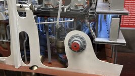
Tto install the aux AEs, I had one more pipe to connect. I had pre-pinned the pipe end and drilled an appropriate hole in the aux steam header.

And attached. The ejectors themselves are epoxied to the rear bulkhead. I used various spring tweezers to hold until epoxy cured.


Took a little while to get the electrical loft into its drilled holes. I had to slightly relieve the rear bulkhead so the escape trunk would pass by the prop shaft seal. Once I found that interference, the unit dropped into place.


When the ladder is in, I will remove the coverings on the base, do the touch up work on it, finish the case and hook up the wiring. Before closing it up I'll take the final "builder's photos" with good lighting and backdrop paper. Meanwhile, enjoy the eye candy. I can't believe when I look at it that I actually drew, printed, painted and aseembled the whote thing. I had about a 30% confidence level going into it.
I added the QR code label to the lower front left corner that steers interested viewers to one of the web forums where I've blogged this entire build. As all of you that have read this from the beginning, if you really want to know how this model came to be, you can find it in the thousands of words in this thread.


I can predict with reasonable certainty that the model will be totally completed by the end of next week. I'd like to schedule delivery sometime in early November before Thanksgiving or early December before the holidays. We'll see how that works out. Once models like this are finished, I don't like keeping them around. I get superstitous about bead things happening to them. That's not to say that wouldn't like to have it around forever, but that's not what this deal was all about. This is not a "private" model just for me to enjoy.
It's going to go here.
To facilitate installatin, I drew and printed the ladder with a bit of framing and grating. It printed right at the end of the session and the print looks successful. I printed only one as I wasn't sure how successful it would be. With its success, I should have printed multiple copies since I invariably break on (or more).
I got the remaining interior ladders installed. I actually didn't need the ones I just printed. The previous ones worked okay.
And the longer Center Ladder (hard to photograph).
From the outside:
And from the top:
But the biggest thing today was getting the electrical decks and the auxiliary air ejectors permanently installed, and with them the model IS COMPLETE—except for that one front ladder.
Tto install the aux AEs, I had one more pipe to connect. I had pre-pinned the pipe end and drilled an appropriate hole in the aux steam header.
And attached. The ejectors themselves are epoxied to the rear bulkhead. I used various spring tweezers to hold until epoxy cured.
Took a little while to get the electrical loft into its drilled holes. I had to slightly relieve the rear bulkhead so the escape trunk would pass by the prop shaft seal. Once I found that interference, the unit dropped into place.
When the ladder is in, I will remove the coverings on the base, do the touch up work on it, finish the case and hook up the wiring. Before closing it up I'll take the final "builder's photos" with good lighting and backdrop paper. Meanwhile, enjoy the eye candy. I can't believe when I look at it that I actually drew, printed, painted and aseembled the whote thing. I had about a 30% confidence level going into it.
I added the QR code label to the lower front left corner that steers interested viewers to one of the web forums where I've blogged this entire build. As all of you that have read this from the beginning, if you really want to know how this model came to be, you can find it in the thousands of words in this thread.
I can predict with reasonable certainty that the model will be totally completed by the end of next week. I'd like to schedule delivery sometime in early November before Thanksgiving or early December before the holidays. We'll see how that works out. Once models like this are finished, I don't like keeping them around. I get superstitous about bead things happening to them. That's not to say that wouldn't like to have it around forever, but that's not what this deal was all about. This is not a "private" model just for me to enjoy.
Attachments
Airframes
Benevolens Magister
Truly amazing work, absolutely stunning !
Vic Balshaw
Major General
It would be a show stopper.
syscom3
Pacific Historian
You sir are not a model builder. You are an artisan!
Great work so far!
- Thread starter
- #490
Builder 2010
Staff Sergeant
Thank you dear readers!
Today is the official day that the MODEL IS DONE! Not the entire display, but the model itself. I started the process of fixing the display base and will complete that tomorrow and later. According to my friend who crafted the base, the finishing process is somewhat slow involving several coats of satin clear and guitar color with 1/2 hour dry times between coats. I bought some more fancy, oval-head brass screws that will hold the brass case clamps in place. I also created one more graphic that now adorns the case. It shows the position of ER #3 relative to the other three. I felt it was needed to add context to the model. The main thing done to day was finish and install that last ladder. It went on much more easily than I expected. Now… that's a surprise!
After cleaning and post-curing, I spray canned Tamiya Silver Leaf for the ladder. When dry, masked and airbrushed Tamiya Semi-gloss Black and then hand brushed the foundation red to the underframe. When all this dried I epoxied it in place and IT'S DONE! The stair is in the foreground on the port (right) side. It needed a little platform to tie it back into the rest of the flooring system. I should have designed that bit in, but alas, did not.


For the refinishing… I had to scrape more of the epoxy strands on the left and fill the ding hole in the middle with Bondic before saning everything smooth. I masked around the Bondic patch so I could use the electric sander, but still caught some of the adjacent woodwork. It should finish pretty well. I'm going to decant the spray can products and use the airbrush to limit the area that's going to get new finish. I'm worried about the blend line.

The graphic that's now on the case is this:

I printed duplicates and adhered them back-to-back. I then attached it to the case with the 3M Transfer Tape as I did with the Item Key. The actual graphic is about 6" wide and a couple deep. It's not going to block viewing anything important. It's quite dramatic about how much of this ship's interior is taken up by propulsion. That's about 300' feet of engines and boilers. Interestingly, the drawing has the layout of ER 3 incorrect. That doesn't matter since the correct one is sitting right in front of their eyes.
The entire model will be finished next week. I'm getting some help to manipulate it since it's big and will be heavy when the case is al closed up. It has to be flipped on its side so I can hook up the LED leads to the power board. The model is pretty strong and should make the journey well, but it can't really handle shocks, so when flipping it, it shouldn't be dropped.
When it ALL done, I will make official builder's photos then open a bottle of Bourbon.
Today is the official day that the MODEL IS DONE! Not the entire display, but the model itself. I started the process of fixing the display base and will complete that tomorrow and later. According to my friend who crafted the base, the finishing process is somewhat slow involving several coats of satin clear and guitar color with 1/2 hour dry times between coats. I bought some more fancy, oval-head brass screws that will hold the brass case clamps in place. I also created one more graphic that now adorns the case. It shows the position of ER #3 relative to the other three. I felt it was needed to add context to the model. The main thing done to day was finish and install that last ladder. It went on much more easily than I expected. Now… that's a surprise!
After cleaning and post-curing, I spray canned Tamiya Silver Leaf for the ladder. When dry, masked and airbrushed Tamiya Semi-gloss Black and then hand brushed the foundation red to the underframe. When all this dried I epoxied it in place and IT'S DONE! The stair is in the foreground on the port (right) side. It needed a little platform to tie it back into the rest of the flooring system. I should have designed that bit in, but alas, did not.
For the refinishing… I had to scrape more of the epoxy strands on the left and fill the ding hole in the middle with Bondic before saning everything smooth. I masked around the Bondic patch so I could use the electric sander, but still caught some of the adjacent woodwork. It should finish pretty well. I'm going to decant the spray can products and use the airbrush to limit the area that's going to get new finish. I'm worried about the blend line.
The graphic that's now on the case is this:
I printed duplicates and adhered them back-to-back. I then attached it to the case with the 3M Transfer Tape as I did with the Item Key. The actual graphic is about 6" wide and a couple deep. It's not going to block viewing anything important. It's quite dramatic about how much of this ship's interior is taken up by propulsion. That's about 300' feet of engines and boilers. Interestingly, the drawing has the layout of ER 3 incorrect. That doesn't matter since the correct one is sitting right in front of their eyes.
The entire model will be finished next week. I'm getting some help to manipulate it since it's big and will be heavy when the case is al closed up. It has to be flipped on its side so I can hook up the LED leads to the power board. The model is pretty strong and should make the journey well, but it can't really handle shocks, so when flipping it, it shouldn't be dropped.
When it ALL done, I will make official builder's photos then open a bottle of Bourbon.

- Thread starter
- #492
Builder 2010
Staff Sergeant
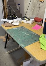
With the model done, the only thing going on is fixing my destruction of the wood base. I put on three coats of finish. First a satin lacquer, a light sanding after 1/2 hour. Then a color coat of Guitar Finish Tobacco Brown, and after another 1/2 hour another coat of satin laquer. I may end with that, although Bryant put on two more satin coats. There's already finish there except for where I sanded it. Depending on your view, the fix looks either good or not-so-hot. My Bondic fix is not completely flush with the surface and the sanding error next to it is a little depression. I am hoping that folks don't even see the base and are fixated on looking at the model.
This is the good view:

And the bad one:

I may try one more coat after another light sanding...
Here's the ER location diagram on the enclosure back wall. Remember it's double sided and can be viewed from both directions.

Tomorrow should have the base fixed and I'll be working on the enclosure locks. I'll be able to take nice images of the model on the base.
This is the good view:
And the bad one:
I may try one more coat after another light sanding...
Here's the ER location diagram on the enclosure back wall. Remember it's double sided and can be viewed from both directions.
Tomorrow should have the base fixed and I'll be working on the enclosure locks. I'll be able to take nice images of the model on the base.
SaparotRob
Unter Gemeine Geschwader Murmeltier XIII
Nice recovery!
- Thread starter
- #495
Builder 2010
Staff Sergeant
IT IS DONE!
There's a load of pictures today in honor of the model's completion.
Day started drilling the case for the two remaining clips. I use masking tape backing to help prevent cracking when the drill breaks through. i used a small pilot hole and then a drill sharpened specifically for plexiglass. The holes were clean.

I fastened the case on so I could tip it over for the wiring.

While it's a bit heavy and unwieldy, I was able to carefully tip it over exposing the underneath.

I use Euro-style electrical hookups with ferrules. I got into this habit when building my model railroad while working for Henkel living in Germany. I terminated all the wiring.

The first two I connected failed to work! I checked for correct voltage from the power supply and for correct polarity of the wiring, but they didn't work. I got a bit worried. These two weren't critical, being the lights under the main steam line that would give more light to the turbines and the other under the evaporator deck lighting up the lube oil purifier. Neither area is actually in the dark.
The next three connections worked perfectly… whew! Here's what they look like under lower ambient lighting. I love how the control console looks when lit.


The aux condenser piping was very obscure until the lights went on.

Even with the room lights on you can still see the illumination.


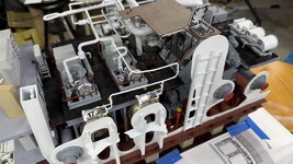
Here are three shots of the completed model with the case cleaned. The model is ready for delivery.


Here's the builder's plate.

And here's all the parts that didn't make it. Some of duplicates. Most are rejects. Lots of trial and error creating this.

So dear readers, let's summarize this undertaking.
The Good:
Three things seemed—at the time—to be show stoppers: the herringbone gears, the turbines and the gratings. I attacked these early on, even before I had John Miano's drawings. The red herring of having drawings at the National Archives that turned out to be the Battleship New Jersey BB16 from 1905 deflated my sails completely. No dimensioned drawings = no project. When John Miano came through with 40 detailed techincal drawings the project was possible; definitely not a sure thing, but at least there was someplace to start. As it came together, drawing-by-drawing, the possibility of a real model got clearer. When I finalized my drawings and produced renderings of what it would look like, all I had to do was put it all together so it came out like I pictured it.
Thanks to all who hung around this thread for 14 months while I ground through this. Your support, feedback and ideas keep me going. It takes about 1/2 hour per night to journal all of this, but it's worth it. I do this thread on four different forums, each with its own focus and participation. As a result, I have folks with whom I have a collegial relationship from all over the world including North America, Europe, Australia and Asia. Of all the bad things you hear about the Internet, the ability to connect with folks like you overshadows all of the negative aspects.
So… what's next? I'm noodling doing the steering gear. It's an interesting and vital area that very few visitors ever see. It hasn't been modeled before, I believe, much like this one, and while less mechanically complex, it is far more geometrically complex which should make it interesting. For example: Do I model one side or both? They're identical. Do I include the rudders? If I include the rudders, do I include the propellers which are an integral part of the system? How do I draw the propellers? I don't know… that's the fun. It could be built on a mirror like is done with ship models all the time. Only problem is the hydraulic pumping units are not mirror images of each other. They are identical.
The other choice could be the Emergency Diesel Generating Room, fore or aft. Aft is a simpler space to model and is the only space in the ship where all four prop shafts are visible. I've already mastered how to support those shafts. The diesel engine, an ALCo 359, is a variation of engines that I've already drawn and printed, so this model could be a little less onerous than my previous forays.
Or perhaps I'll take a break for a while and build something for my train layout, which has been sad since I've been neglecting it all year. We'll see… Stay tuned.
There's a load of pictures today in honor of the model's completion.
Day started drilling the case for the two remaining clips. I use masking tape backing to help prevent cracking when the drill breaks through. i used a small pilot hole and then a drill sharpened specifically for plexiglass. The holes were clean.
I fastened the case on so I could tip it over for the wiring.
While it's a bit heavy and unwieldy, I was able to carefully tip it over exposing the underneath.
I use Euro-style electrical hookups with ferrules. I got into this habit when building my model railroad while working for Henkel living in Germany. I terminated all the wiring.
The first two I connected failed to work! I checked for correct voltage from the power supply and for correct polarity of the wiring, but they didn't work. I got a bit worried. These two weren't critical, being the lights under the main steam line that would give more light to the turbines and the other under the evaporator deck lighting up the lube oil purifier. Neither area is actually in the dark.
The next three connections worked perfectly… whew! Here's what they look like under lower ambient lighting. I love how the control console looks when lit.
The aux condenser piping was very obscure until the lights went on.
Even with the room lights on you can still see the illumination.
Here are three shots of the completed model with the case cleaned. The model is ready for delivery.
Here's the builder's plate.
And here's all the parts that didn't make it. Some of duplicates. Most are rejects. Lots of trial and error creating this.
So dear readers, let's summarize this undertaking.
The Good:
- Without the drawings this project would have been impossibe.
- The Swiss Cheese design of having the bulkheads there, but not there, worked better than I expected.
- Learning how to draw large herringbone gears, turbine blades, etc. pushed my creative envelope.
- The arrival of my Elegoo Saturn 4 Ultra printer at the onset of the project was fortuitous, doing everything I asked it do and it never ceased to amaze me.
- Pre-planning the lighting—even though two ciruits didn't work—worked well and made my life easier.
- Laying out and fitting all of this machinery and piping is a small space was the biggest challenge that I overcame.
- Including the triple bottom, while a complete pain in the butt to execute, was an important feature of this part of the ship that needed inclusion
- The arrival of the vinyl cutter in the middle of the project solved the problem of identifying all the apparatus and striping the propeller shafts. I will find more things for this tool to do on future projects.
- The failed circuits were the least important.
- Using water pipe to simulate the other propeller shafts worked very well.
- Building a model like this from photos of the real engine room was almost impossible and yet, those photos were invaluable in creating the model. While I had a lot of drawings, I still had to design parts from photos only.
- My case building skills are still wanting. I think I'm going to outsource this on future projects.
- My Apple MacBook Pro 2019 is not up to the task of designing massive 3D models. I want to make an animated walk through of the model for uploading to Youtube, but this machine can't do it.
- Desiging the model with the full lattice bottom framing was overkill and could be greatly streamlined if ever make another one of these, which I don't think will happen.
- Hand cutting all the lattice pieces was far more effort than the value it created for the model.
- Even with all the drawings being checked and rechecked, I still missed things like that last stair.
- I'm not happy with the paint finish on a few things especially the piping. My airbrushing was inconsistent.
- Why two lighting circuits failed after checking them multiple times off the model is a mystery. It's possible that the brass tubing cut the insulation and shorted them out.
- Decal application was okay. Could have been better.
- There's excess glue in places that were impossible to reach, but are now illuminated and visible.
- Getting the sub-asssemblies to settle down was very difficult. There were times when I thought it wouldn't work.
Three things seemed—at the time—to be show stoppers: the herringbone gears, the turbines and the gratings. I attacked these early on, even before I had John Miano's drawings. The red herring of having drawings at the National Archives that turned out to be the Battleship New Jersey BB16 from 1905 deflated my sails completely. No dimensioned drawings = no project. When John Miano came through with 40 detailed techincal drawings the project was possible; definitely not a sure thing, but at least there was someplace to start. As it came together, drawing-by-drawing, the possibility of a real model got clearer. When I finalized my drawings and produced renderings of what it would look like, all I had to do was put it all together so it came out like I pictured it.
Thanks to all who hung around this thread for 14 months while I ground through this. Your support, feedback and ideas keep me going. It takes about 1/2 hour per night to journal all of this, but it's worth it. I do this thread on four different forums, each with its own focus and participation. As a result, I have folks with whom I have a collegial relationship from all over the world including North America, Europe, Australia and Asia. Of all the bad things you hear about the Internet, the ability to connect with folks like you overshadows all of the negative aspects.
So… what's next? I'm noodling doing the steering gear. It's an interesting and vital area that very few visitors ever see. It hasn't been modeled before, I believe, much like this one, and while less mechanically complex, it is far more geometrically complex which should make it interesting. For example: Do I model one side or both? They're identical. Do I include the rudders? If I include the rudders, do I include the propellers which are an integral part of the system? How do I draw the propellers? I don't know… that's the fun. It could be built on a mirror like is done with ship models all the time. Only problem is the hydraulic pumping units are not mirror images of each other. They are identical.
The other choice could be the Emergency Diesel Generating Room, fore or aft. Aft is a simpler space to model and is the only space in the ship where all four prop shafts are visible. I've already mastered how to support those shafts. The diesel engine, an ALCo 359, is a variation of engines that I've already drawn and printed, so this model could be a little less onerous than my previous forays.
Or perhaps I'll take a break for a while and build something for my train layout, which has been sad since I've been neglecting it all year. We'll see… Stay tuned.
Attachments
Vic Balshaw
Major General
Myles it has been an absolute privilege watching the amazing model come together. You are a master in your class and thank you so much for sharing this adventure with us. 
Excellent work so far!
Wonderful 
N4521U
Plastic Pirate
The ral shame is.............
the casual onlooker will never know the struggle,
the massive effort you put in for this project.
UNbelievable what you have accomplished!
Bravo
the casual onlooker will never know the struggle,
the massive effort you put in for this project.
UNbelievable what you have accomplished!
Bravo
Users who are viewing this thread
Total: 2 (members: 0, guests: 2)