Nice work so far!
Navigation
Install the app
How to install the app on iOS
Follow along with the video below to see how to install our site as a web app on your home screen.
Note: This feature may not be available in some browsers.
More options
You are using an out of date browser. It may not display this or other websites correctly.
You should upgrade or use an alternative browser.
You should upgrade or use an alternative browser.
1/48 Hobby Craft Boeing P-26A
- Thread starter Grant Barr
- Start date
Ad: This forum contains affiliate links to products on Amazon and eBay. More information in Terms and rules
More options
Who Replied?fubar57
General
Lovely work
Lucky13
Forum Mascot
- Thread starter
- #24
Grant Barr
Senior Airman
Having now finished and broken my Corsair, I'm now back to the P-26 and keen to get this one finished as well (but preferably not broken afterwards...). In an earlier post I mentioned the difficulty with the exhausts - having to remove them from the sprue to allow access to the outlet ends for drilling out. The challenge was how to hold onto them whilst opening them out. Andy did suggest a hobby vice, which I have, but find it's a bit "sloppy" in alignment and would struggle to hold onto such a small piece. I also looked at using brass tube, but found that I could not stretch the ends out to the oval shape required - at least not without splitting the tube.
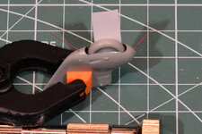
The final solution was very simple. My spring clamps have orange end plates with a tiny little groove right down the middle. Pop the engine end of the pipe into this groove and go to work!! Here you can see I've drilled out the 5 single pipes and the double collector pipe - I've got the final single pipe almost done in this shot and mounted in the spring clamp as described.

Have to call it a night unfortunately, but tomorrow is a public holiday in Oz so am hoping to get some more done on the Peashooter.
As always, thanks for looking in on my latest project. Cheers!
The final solution was very simple. My spring clamps have orange end plates with a tiny little groove right down the middle. Pop the engine end of the pipe into this groove and go to work!! Here you can see I've drilled out the 5 single pipes and the double collector pipe - I've got the final single pipe almost done in this shot and mounted in the spring clamp as described.
Have to call it a night unfortunately, but tomorrow is a public holiday in Oz so am hoping to get some more done on the Peashooter.
As always, thanks for looking in on my latest project. Cheers!
Crimea_River
Marshal
Those look really good Grant. Good solution.
Lovely work so far Grant!
southerndoug
Airman
That sure is some delicate work there Grant! Impressive!
Prop Duster
Airman
Very well done. It always is a nice surprise to find the solution to an assembly question is the simple thing vs the big flashy, sometimes pricy "official modeling tools"
- Thread starter
- #30
Grant Barr
Senior Airman
I'm a bit later with this updated than planned - but I have not been idle. In some reference photos I noticed that the fuselage panels immediately behind the engine actually reach up in between the cylinders. None of the photos I have been able to find show the aircraft with the engine ring cowl removed so getting exact details on the shape and length of these panels is difficult. Despite this unknown I decided to fabricate some panels from 0.013mm styrene sheet and fit them as the next step.
The current state is as shown below. They have been cut and fitted with a small backing piece to ensure that we have a reasonably robust join to the fuselage. These shots were taken as I wait for the glue to cure some more before trimming and shaping the panels to fit properly between the cylinders and inlet/exhaust lines.
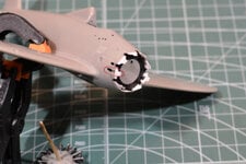
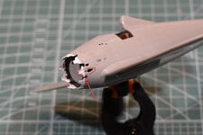
I've circled the two panels in the photos that will require the most surgery. Both of these panels will need to be cut away to allow the gun barrels to protrude up between the cylinders. All the others will require some "customisation" to ensure the engine fits properly when it's time to do so.
As I noted - they will likely not be 100% accurate in shape and size but I am hoping that the small details like this will help make the model just that little bit more representative of the real thing. I'm also investigating how to make the fluted vents in the fuselage look more lifelike. I've got a plan - just need to test it out (most likely on the vents under the fuselage).
Thanks for the kind words of support, this one has been fun so far. I'm hoping the motivation stays strong once I get to painting and finishing - always seems to be a struggle point for me.
Cheers!
The current state is as shown below. They have been cut and fitted with a small backing piece to ensure that we have a reasonably robust join to the fuselage. These shots were taken as I wait for the glue to cure some more before trimming and shaping the panels to fit properly between the cylinders and inlet/exhaust lines.


I've circled the two panels in the photos that will require the most surgery. Both of these panels will need to be cut away to allow the gun barrels to protrude up between the cylinders. All the others will require some "customisation" to ensure the engine fits properly when it's time to do so.
As I noted - they will likely not be 100% accurate in shape and size but I am hoping that the small details like this will help make the model just that little bit more representative of the real thing. I'm also investigating how to make the fluted vents in the fuselage look more lifelike. I've got a plan - just need to test it out (most likely on the vents under the fuselage).
Thanks for the kind words of support, this one has been fun so far. I'm hoping the motivation stays strong once I get to painting and finishing - always seems to be a struggle point for me.
Cheers!
fubar57
General
Very nice
- Thread starter
- #33
Grant Barr
Senior Airman
Been really busy with this kit - but have so little to show for all the time...
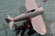
I've now blended in my engine panel extensions with a bit of liquid filler and some light sanding and shaping. I've also done a lot of trimming and sanding to make sure that the engine fits snugly amongst the new panels. They'll only be seen from a few angles but I know they will add to the final look of the kit.
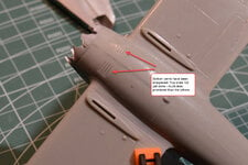
I've also started work on the pressed flute vents on the lower side of the fuselage. Apologies for the lousy photography - I tried to change my lighting a bit so it throws some shadows across the flutes - with limited success. Essentially the lower flutes in the photo are cleaned up and sharpened whilst the top ones are not. The difference is noticeable IRL and I hope is enough to be picked up with photos once painted and detailed.
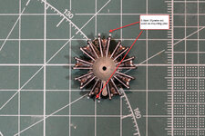
I've also done a fair bit of work on getting the engine fit to the cowl ring right. The kit has four tiny locating lugs molded into the top and bottom of the engine that, in theory, align to some holes molded into the cowl. No surprise - they don't line up and the lugs are too small - meaning the cowl cannot be properly secured and/or centred around the engine. So to fix I cut off the molded lugs and drilled some holes to fit some 0.6mm styrene rod, which I've highlighted with the arrows as they can be a bit hard to see. This gave me the chance cut and fit them to the proper length and ensure that the engine now sits in the centre of the cowl with a positive fit for the lugs.
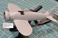
What I didn't realise up to this point was that the molded holes seem to be too far back on the cowl ring and they don't ensure that the cowl sits straight across the engine/fuselage, as you can see in the photo below. It's nothing that can't be fixed, it will just require a bit more patience and maybe a couple more lugs to be added to the engine. I'm also toying with inserting a flat styrene strap around the inside of the cowl panel. This will have a double purpose, firstly to provide more depth to add more accurately placed holes for the engine mount lugs, and second provide some additional strength for the butt joints for the two cowl halves. It should be reasonably strong without this, but I will be happier if I can find a way to ensure the cowl is as strong as possible - I tend to break things (as my Corsair is testament...).
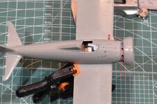
The final thing I noticed when mocking up the engine was the port side exhaust seems to stick out way too far. The photo above shows just how far it sticks out - it sort of looks out of scale with the rest of the aircraft. I've got some drawings saved somewhere on my cloud drive, I'll have to dig them out to see what it should look like.
That's about all I have to report at this point. Still having fun and really enjoying making this old kit hopefully(?) look just a little bit better than it would built OOB.
Thanks again for looking in. As always comments/suggestions/feedback is most welcome.

I've now blended in my engine panel extensions with a bit of liquid filler and some light sanding and shaping. I've also done a lot of trimming and sanding to make sure that the engine fits snugly amongst the new panels. They'll only be seen from a few angles but I know they will add to the final look of the kit.

I've also started work on the pressed flute vents on the lower side of the fuselage. Apologies for the lousy photography - I tried to change my lighting a bit so it throws some shadows across the flutes - with limited success. Essentially the lower flutes in the photo are cleaned up and sharpened whilst the top ones are not. The difference is noticeable IRL and I hope is enough to be picked up with photos once painted and detailed.

I've also done a fair bit of work on getting the engine fit to the cowl ring right. The kit has four tiny locating lugs molded into the top and bottom of the engine that, in theory, align to some holes molded into the cowl. No surprise - they don't line up and the lugs are too small - meaning the cowl cannot be properly secured and/or centred around the engine. So to fix I cut off the molded lugs and drilled some holes to fit some 0.6mm styrene rod, which I've highlighted with the arrows as they can be a bit hard to see. This gave me the chance cut and fit them to the proper length and ensure that the engine now sits in the centre of the cowl with a positive fit for the lugs.

What I didn't realise up to this point was that the molded holes seem to be too far back on the cowl ring and they don't ensure that the cowl sits straight across the engine/fuselage, as you can see in the photo below. It's nothing that can't be fixed, it will just require a bit more patience and maybe a couple more lugs to be added to the engine. I'm also toying with inserting a flat styrene strap around the inside of the cowl panel. This will have a double purpose, firstly to provide more depth to add more accurately placed holes for the engine mount lugs, and second provide some additional strength for the butt joints for the two cowl halves. It should be reasonably strong without this, but I will be happier if I can find a way to ensure the cowl is as strong as possible - I tend to break things (as my Corsair is testament...).

The final thing I noticed when mocking up the engine was the port side exhaust seems to stick out way too far. The photo above shows just how far it sticks out - it sort of looks out of scale with the rest of the aircraft. I've got some drawings saved somewhere on my cloud drive, I'll have to dig them out to see what it should look like.
That's about all I have to report at this point. Still having fun and really enjoying making this old kit hopefully(?) look just a little bit better than it would built OOB.
Thanks again for looking in. As always comments/suggestions/feedback is most welcome.

Looks good so far!
Crimea_River
Marshal
Great update. Looking pretty good.
- Thread starter
- #37
Grant Barr
Senior Airman
Latest update. For a couple of days now I have been trying to determine how I can resolve a problem with the undercarriage assembly for this kit. The way the kit is designed means that you must trap the wheel between the two halves of the landing gear spats. Of course this means that the interior of the spat and the wheels must be painted before assembly and then masked very carefully once I get to final painting and detailing. The instructions show how the undercarriage is meant to be:
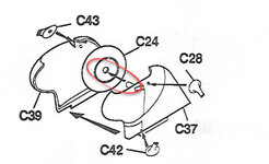
As you can see there is a shaft moulded into the spat onto which you can glue the main wheel. This has to be done before joining the two spat halves as there is no room to insert the wheel past the shaft. I really don't want to put the wheel in before painting so a solution had to be decided on.
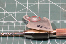
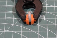
I thought the best fix was to reverse the shaft location and then put a mounting cup (half circle) in the spat that the shaft can drop into. The two shots below show the inside of the spat where I have removed the shaft and glued a very small half circle (basically some styrene rod cut in half) that has an internal diameter of 2mm to match the diameter of the shaft I have now fitted to the wheel, as shown.
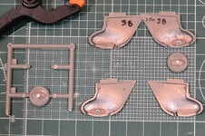
The next shot shows the fix in place on the starboard spat and the work in progress for the port spat. As you may imagine there is a lot of shaping, fitting, shaping some more and fitting some more to make sure the wheel ends up in the right place both vertically and laterally within the wheel slot.
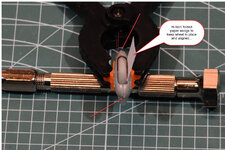
The final shots show the starboard spat mocked up with the wheel dropped into its place in the cup. To make sure the wheel is lined up laterally within the spat I used a high tech piece of folded paper to make sure it was pushed solidly across into the cup and can be lined up properly. I've highlighted in the lateral shot how the wheel is very slightly skewed in the hole - will need to make sure it is straight once finally glued into place after painting. The other thing I noticed, and have pointed out in these photos is that the alignment of the two spat halves is just a tiny bit out. I'll either remove the two locating lugs or maybe just trim them a little bit to make sure the halves line up and no gaps or seams are apparent once glued.
That's pretty much brought you all up to date with progress. I have also done some other work on some of the final detail bits to be added once painting and decalling is done. If I get a minute or two spare I will take some photos of this work to share.
Thank you to everyone again for comments and feedback.

As you can see there is a shaft moulded into the spat onto which you can glue the main wheel. This has to be done before joining the two spat halves as there is no room to insert the wheel past the shaft. I really don't want to put the wheel in before painting so a solution had to be decided on.
I thought the best fix was to reverse the shaft location and then put a mounting cup (half circle) in the spat that the shaft can drop into. The two shots below show the inside of the spat where I have removed the shaft and glued a very small half circle (basically some styrene rod cut in half) that has an internal diameter of 2mm to match the diameter of the shaft I have now fitted to the wheel, as shown.


The next shot shows the fix in place on the starboard spat and the work in progress for the port spat. As you may imagine there is a lot of shaping, fitting, shaping some more and fitting some more to make sure the wheel ends up in the right place both vertically and laterally within the wheel slot.

The final shots show the starboard spat mocked up with the wheel dropped into its place in the cup. To make sure the wheel is lined up laterally within the spat I used a high tech piece of folded paper to make sure it was pushed solidly across into the cup and can be lined up properly. I've highlighted in the lateral shot how the wheel is very slightly skewed in the hole - will need to make sure it is straight once finally glued into place after painting. The other thing I noticed, and have pointed out in these photos is that the alignment of the two spat halves is just a tiny bit out. I'll either remove the two locating lugs or maybe just trim them a little bit to make sure the halves line up and no gaps or seams are apparent once glued.


That's pretty much brought you all up to date with progress. I have also done some other work on some of the final detail bits to be added once painting and decalling is done. If I get a minute or two spare I will take some photos of this work to share.
Thank you to everyone again for comments and feedback.
Crimea_River
Marshal
Good solution Grant.
SaparotRob
Unter Gemeine Geschwader Murmeltier XIII
If your not part of the solution then you are part of the precipitate.
Users who are viewing this thread
Total: 1 (members: 0, guests: 1)
