Nice one!
Navigation
Install the app
How to install the app on iOS
Follow along with the video below to see how to install our site as a web app on your home screen.
Note: This feature may not be available in some browsers.
More options
You are using an out of date browser. It may not display this or other websites correctly.
You should upgrade or use an alternative browser.
You should upgrade or use an alternative browser.
Adelaide Model Expo (2009)
- Thread starter Wayne Little
- Start date
Ad: This forum contains affiliate links to products on Amazon and eBay. More information in Terms and rules
More options
Who Replied?Bullo Loris
Senior Airman
- 334
- Oct 14, 2006
An other super nice kit ")
Crimea_River
Marshal
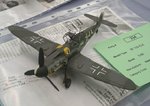
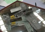
That's certainly different! Nicely done!
Matt308
Glock Perfection
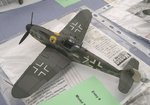
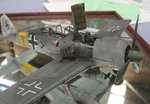
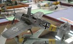
I love the camo on the 126!! The aerial was attached to the rudder?? Note that the attachment point is on in alignment with the hinge and thus would create tension on the aerial unless pre-slackened. Is this correct?
- Thread starter
- #485

Nice one!
Crimea_River
Marshal
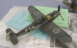
Agreed. Clean work.
kgambit
Tech Sergeant
I love the camo on the 126!! The aerial was attached to the rudder?? Note that the attachment point is on in alignment with the hinge and thus would create tension on the aerial unless pre-slackened. Is this correct?
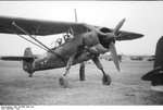
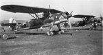
Yep. That's correct. Look at these pics (especially the second one).
Attachments
- Thread starter
- #489
Well!! there ya go...Thanks Dwight!
kgambit
Tech Sergeant
Well!! there ya go...Thanks Dwight!
You're welcome Wayne.
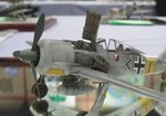
Matt, that connection point will actually INDUCE slack in the antenna wire when the rudder is pivoted and not increase tension. For the sake of argument, assume that the antenna wire is 100 inches long with 5 inches of that being the portion that extends past the rudder pivot. If you turn the rudder ninety degrees in either direction, the distance between the connection points is SQRT (95^2 + 5^2) = 95.13" - so the distance between the connection points decreases and the line goes slack. Make no difference what dimensions you assume.
Last edited:
- Thread starter
- #491


Good one!
Matt308
Glock Perfection
You're welcome Wayne.
Matt, that connection point will actually INDUCE slack in the antenna wire when the rudder is pivoted and not increase tension. For the sake of argument, assume that the antenna wire is 100 inches long with 5 inches of that being the portion that extends past the rudder pivot. If you turn the rudder ninety degrees in either direction, the distance between the connection points is SQRT (95^2 + 5^2) = 95.13" - so the distance between the connection points decreases and the line goes slack. Make no difference what dimensions you assume.
That's my point. If you look at the model, the antenna is not slackened, yet the rudder is depicted with deflection. Thus, when the rudder returns to it's neutral position it will create tension in the aerial. I was wondering if this was a correction representation by the modeler based upon some mechanical tensioner in the -126 or if it was an oversight. Anyway, thanks guys, I think I can deduce my answer. Back at it Wayne!!
kgambit
Tech Sergeant
That's my point. If you look at the model, the antenna is not slackened, yet the rudder is depicted with deflection. Thus, when the rudder returns to it's neutral position it will create tension in the aerial. I was wondering if this was a correction representation by the modeler based upon some mechanical tensioner in the -126 or if it was an oversight. Anyway, thanks guys, I think I can deduce my answer. Back at it Wayne!!
Sorry - must have misunderstood.
We now return to our regularly scheduled programming.
- Thread starter
- #495
Excellent!
Airframes
Benevolens Magister
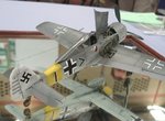
Quite nice, but I think the modeller has used the wrong canopy perhaps? Eduard's A8 at least has two canopies, one for the open position, allowing it to sit correctly on the 'rails' without showing a gap.
Crimea_River
Marshal
Nice kit and a fine job. Not sure if its the lens but the dihedral looks wierd to me.
Airframes
Benevolens Magister
Yep, I thought that too, but didn't wish to appear too crtical !!!
- Thread starter
- #500
Users who are viewing this thread
Total: 1 (members: 0, guests: 1)