American bombers and transport aircrafts

Ad: This forum contains affiliate links to products on Amazon and eBay. More information in Terms and rules

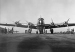
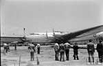
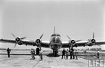
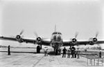
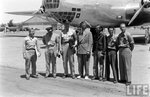
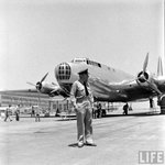
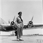
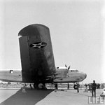
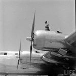
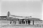
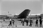
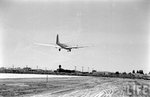
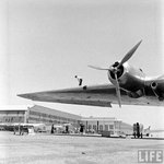
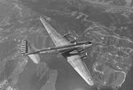
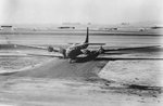
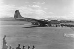
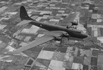
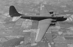
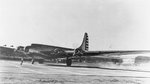
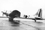
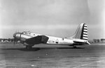
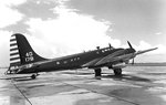
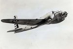
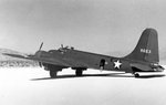
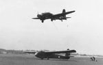
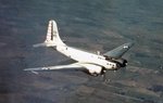
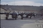
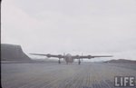
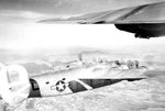
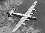
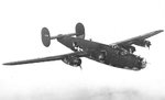
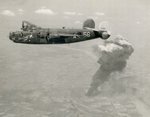
The Douglas XB-19 was the largest American aircraft built until the completion of the Convair B-36 in August of 1946. The XB-19 project had its origin in a secret Army Air Corps project of the mid 'thirties for an advanced long-range bomber. On February 5, 1935, the Army Air Corps initiated a secret project for an experimental long-range bomber, with the goal of seeing just how far the state of the art could be pushed. It was assigned the codename "Project D", and was classified top secret. No production was envisaged, since "Project D" was more of a proof-of-concept vehicle than it was a serious proposal for a production military aircraft.

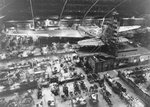
Preliminary discussions were carried out with Douglas and Sikorsky, the only two companies which showed any interest in participating in the project. The Army wanted the prototype to be delivered by March 31, 1938. On July 9, 1935, the designation XBLR-2 was assigned to the Douglas proposal, the type symbol BLR standing for Bomber, Long Range. The BLR type symbol had been introduced in 1935 to cover large, long-range bombers. At the same time, the competing Sikorsky design was assigned the designation XBLR-3. A contract covering preliminary and detailed design, mock-up construction and testing of critical components was sent to Douglas in October of 1935 and was approved on October 18.

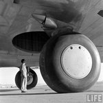
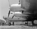
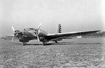
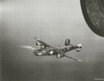
In March of 1936, wooden mockups of the Douglas and Sikorsky designs were inspected. At that time, the Douglas proposal was deemed superior, and the contract for the Sikorsky XBLR-3 was cancelled. Progress on the XBLR-2 proceeded rather slowly due to the shortage of funds caused by the limited military budget allocated for research and development during the Depression years 1935 to 1937. The aircraft was conceived as a large, four-engined, low-winged monoplane. A tricycle undercarriage was to have been fitted, which was still rather unusual for the time. This undercarriage was tested on a Douglas OA-4B Dolphin amphibian loaned back to the company by the Army.

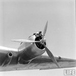
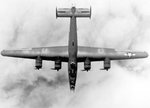
The XBLR-2 was originally to have been powered by four 1600 hp Allison XV-3420-1 twenty-four cylinder liquid-cooled engines. The XV-3420 was basically a pair of V-1710 twelve-cylinder liquid-cooled Vee engines coupled together to drive a single propeller. On November 2, 1936, the Douglas company decided to substitute the 2000 hp Wright R-3350 air-cooled radial for the coupled Allisons originally specified. The separate BLR type symbol was abolished in 1936, and the XBLR-2 was redesignated B-19 in the B-for-bomber series. By late 1937, enough R D funds had been made available so that a contract change calling for the construction of a single prototype under the designation XB-19 was issued on November 19, 1937, but not approved until March 8, 1938. The serial number 38-471 was assigned.
 

Attachments

  • Boeing XB-19 001.jpg
    Boeing XB-19 001.jpg
    83 KB · Views: 307
  • Boeing XB-19 0014.jpg
    Boeing XB-19 0014.jpg
    90.5 KB · Views: 302
  • Boeing XB-19 0015.jpg
    Boeing XB-19 0015.jpg
    82.1 KB · Views: 273
  • Boeing XB-19 0016.jpg
    Boeing XB-19 0016.jpg
    81.3 KB · Views: 280
  • Boeing XB-19 0017.jpg
    Boeing XB-19 0017.jpg
    110.6 KB · Views: 276
By late 1938, the XB-19 was way behind schedule because of the lack of adequate development funds from the USAAC. The Douglas company had been forced to spend a considerable amount of its own money on the XB-19 project and badly needed the XB-19 design staff to work on other aircraft projects that had better prospects for a production future. By this time, the weight of the XB-19 was increasing excessively, resulting in an expectation of a progressively poorer and poorer performance with the engines specified. During the previous three years the advances in the state of the art had been so rapid that the basic B-19 design was by this time quite obsolescent. Consequently, on August 30, 1938 the company recommended to the Army that the XB-19 contract be cancelled.

However, the Army's Materiel Division refused to abandon the project, and construction of the first prototype continued slowly at Douglas. In 1940, the Army, perhaps recognizing that the XB-19 had by that time lost most if not all of its military importance, finally removed the aircraft from its list of secret projects, and the aircraft became a hot item in the popular press as a radically new long-range bomber for America's defense against foreign foes. The XB-19 was finally completed in May of 1941. It was a very large, all-metal stressed-skin low-winged monoplane with a retractable tricycle undercarriage. It had a wingspan of 212 feet and a maximum gross weight of 162,000 pounds. It was physically the largest American aircraft yet built, and was to remain so until the completion of the Convair B-36 in 1946.

The XB-19 was powered by four Wright R-3350-5 eighteen-cylinder air-cooled radials rated at 2000 hp each for takeoff. They drove three-bladed constant-speed propellers. Total internal fuel capacity was 10,350 US gallons, with provision for the fitting of additional tanks of 824 gallon capacity in the bomb bay for additional range. Bombs could be carried either in an internal bomb bay or on ten underwing racks. The internal bomb bay could accommodate eight 2000-pound, 16 1100-pounds, or 30 600-pound bombs. The ten underwing racks could each accommodate bombs of up to 2000 pounds in weight for short-range missions. Maximum bomb capacity was 37,100 pounds.

Defensive armament of the XB-19 (not fitted at the time of completion) was quite heavy for the time. It consisted of one 37-mm cannon and one 0.30-inch machine gun in each of the nose and forward dorsal turrets, one 0.5-inch machine gun in the tail position, rear dorsal turret, ventral turret, and port and starboard positions. One 0.30-inch machine gun was fitted on each side of the bombardier's position and on each side of the fuselage below the tailplane. There was no armor protection for the crew and there were no self-sealing fuel tanks included, but these features would undoubtedly have to have been included had the B-19 ever gone into production.
 

Attachments

  • Boeing XB-19 0019.jpg
    Boeing XB-19 0019.jpg
    120.7 KB · Views: 286
  • Boeing XB-19 0018.jpg
    Boeing XB-19 0018.jpg
    126.8 KB · Views: 300
  • Boeing XB-19 0013.jpg
    Boeing XB-19 0013.jpg
    131.6 KB · Views: 297
  • Boeing XB-19 0012.jpg
    Boeing XB-19 0012.jpg
    121.8 KB · Views: 269
  • Boeing XB-19 0011.jpg
    Boeing XB-19 0011.jpg
    102.9 KB · Views: 295
The normal combat crew of the XB-19 was 16, which included a pilot, co-pilot, aircraft commander, navigator, flight engineer, radio operator, bombardier, a gunner operating the nose power turret, a gunner who operated 0.30-inch guns pointing from each side of the nose compartment, a gunner operating the forward dorsal power turret, an upper rear dorsal turret gunner, two waist gunners, a belly gunner, a tail gunner, and a gunner seated below the stabilizer operating 0.30-inch guns firing from either side of the aircraft. However, an additional crew consisting of 2 flight mechanics and six relief crewmembers could be carried in a special compartment installed in the fuselage above the bomb bay with eight seats and six bunks. Passages in the lower wing gave mechanics direct access to the engines while the aircraft was in flight. The XB-19 even had a complete galley for the inflight preparation of hot meals.

Over three years behind the original schedule, the first flight of the XB-19 took place from Clover Field in Santa Monica on June 27, 1941 with a crew of seven captained by Major Stanley M. Umstead. On its first flight, it was flown to March Field and turned over to the Army for evaluation. Such was the degree of popular enthusiasm aroused by the XB-19 that President Franklin Roosevelt himself telegraphed congratulations to Donald Douglas for this achievement. Thirty hours of manufacturer's flight tests were carried out at March Field before the XB-19 was tentatively accepted by the Army in October of 1941. After the attack on Pearl Harbor on December 7, 1941, as a matter of precaution the XB-19 was painted in camouflage and its guns were loaded during its last four test flights in California. On January 23, 1942, the XB-19 was transferred to Wright Field in Dayton, Ohio, hopefully well out of range of any attacking Japanese aircraft.

After more tests and the carrying out of some minor modifications which included the installation of improved brakes, the aircraft was formally accepted by the Army in June of 1942. The Army paid Douglas $1,400,064 for the XB-19. However, the company had spent almost 4 million dollars of its own funds on the project, so Douglas managed to lose money on the XB-19. Nevertheless, the XB-19 proved on tests to be relatively trouble-free, with the exception of engine cooling difficulties. These problems required that the engine cooling gills be kept open during long flights, reducing maximum speed at 15,700 feet from 224 mph to 204 mph.
 

Attachments

  • Boeing XB-19 0021.jpg
    Boeing XB-19 0021.jpg
    108.9 KB · Views: 288
  • Boeing XB-19 0022.jpg
    Boeing XB-19 0022.jpg
    118.7 KB · Views: 272
  • Boeing XB-19 0023.jpg
    Boeing XB-19 0023.jpg
    102.8 KB · Views: 292
  • Boeing XB-19 0024.jpg
    Boeing XB-19 0024.jpg
    102.5 KB · Views: 282
  • Boeing XB-19 0025.jpg
    Boeing XB-19 0025.jpg
    91.3 KB · Views: 296
Following the completion of its series of flight tests, the XB-19 was eventually modified at Wright Field as a cargo aircraft and fitted with four 2600 hp Allison V-3420-11 turbosupercharged twenty-four cylinder liquid cooled engines, which was the production version of the engine that had originally been specified for the aircraft. It was redesignated XB-19A. The XB-19A could reach a maximum speed of 275 mph and was no longer plagued with engine cooling problems. Although the XB-19/XB-19A never saw production, it provided extremely valuable data for features which were later incorporated into the design of other large aircraft such as the Boeing B-29 and Convair B-36.

The XB-19A made its last flight on August 17, 1946, when it was flown from Wright Field to Davis-Monthan Field in Arizona and placed in storage. It was scrapped there in June of 1949. However, its nose section somehow ended up in a scrap yard on Alameda Street in Los Angeles, and was still visible there as late as 1955. It is too bad that this aircraft could not have been saved.

Specification of Douglas XB-19:

Four Wright R-3350-5 eighteen-cylinder air-cooled radials rated at 2000 hp each for takeoff and 1500 hp at 15,700 feet. Maximum speed 224 mph at 15,700 feet. Cruising speed 135 mph. Initial climb rate 650 feet per minute. Service ceiling 23,000 feet. Normal range 5200 miles, maximum range 7710 miles. Weights: 86,000 pounds empty, 140,000 pounds loaded, 162,000 pounds maximum. Dimensions: wingspan 212 feet, length 132 feet 4 inches, height 42 feet, wing area 4285 square feet. The internal bomb bay could accommodate eight 200-pound, 16 1100-pounds, or 30 600-pound bombs. Ten underwing racks could accommodate bombs of up to 2000 pounds in weight for short-range missions, for a maximum bomb capacity of 37,100 pounds. Defensive armament consisted of two 37-mm cannon, six 0.30 and five 0.50-in machine guns, distributed as follows: one 37-mm cannon and one 0.30-inch machine gun in each of the nose and forward dorsal turrets, one 0.5-inch machine gun in the tail position, rear dorsal turret, ventral turret, and port and starboard positions. One 0.30-inch machine gun was fitted on each side of the bombardier's position and on each side of the fuselage below the tailplane.

Specification of Douglas XB-19A:

Four 2600 hp Allison V-3420-11 twenty-four cylinder liquid cooled engines. Maximum speed 265 mph at 20,000 feet. Cruising speed 185 mph. Service ceiling 39,000 feet. Normal range 4200 miles Weights: 92,400 pounds empty, 140,230 pounds loaded. Dimensions: wingspan 212 feet, length 132 feet 4 inches, height 42 feet, wing area 4285 square feet.
 

Attachments

  • Boeing XB-19 0027.jpg
    Boeing XB-19 0027.jpg
    94.7 KB · Views: 284
  • Boeing XB-19 0026.jpg
    Boeing XB-19 0026.jpg
    133.5 KB · Views: 286
  • Boeing XB-19 005.jpg
    Boeing XB-19 005.jpg
    107.4 KB · Views: 296
  • Boeing XB-19 004.jpg
    Boeing XB-19 004.jpg
    167.5 KB · Views: 297
  • Boeing XB-19 003.jpg
    Boeing XB-19 003.jpg
    96.5 KB · Views: 265
More Pics
 

Attachments

  • Boeing XB-19 002.jpg
    Boeing XB-19 002.jpg
    69.7 KB · Views: 288
  • Boeing XB-19 003.jpg
    Boeing XB-19 003.jpg
    96.5 KB · Views: 284
  • Boeing XB-19 007.jpg
    Boeing XB-19 007.jpg
    118.5 KB · Views: 270
  • Boeing XB-19 008.jpg
    Boeing XB-19 008.jpg
    81.7 KB · Views: 275
  • Boeing XB-19 009.jpg
    Boeing XB-19 009.jpg
    66.2 KB · Views: 283
The Douglas B-18, which had been designed to meet a US Army Air Corps requirement of 1934 for a high-performance medium bomber, was clearly not in the same league as the Boeing B-17 Flying Fortress, which had been built to the same specification. Figures highlight the facts: 350 B-18s were procured in total, by comparison with almost 13,000 B-17s. In an attempt to rectify the shortcomings of their DB-1 design, Douglas developed in 1938 an improved version and the proposal seemed sufficiently attractive for the US Army to award a contract for 38 of these aircraft under the designation B-23 and with the name Dragon.

Although the overall configuration was similar to that of the earlier aircraft, when examined in detail it was seen to be virtually a new design. Wing span was increased, the fuselage was entirely different and of much improved aerodynamic form, and the tail unit had a much higher vertical fin and rudder. Landing gear was the same retractable tailwheel type, but the engine nacelles had been extended so that when the main units were lowered in flight they were faired by the nacelle extensions and created far less drag. Greatly improved performance was expected from these refinements, plus the provision of 60 per cent more power by the use of two Wright R-2600-3 Cyclone 14 engines. An innovation was the provision of a tail gun position, this being the first US bomber to introduce such a feature.
 

Attachments

  • Douglas B-23 Dragon 006.jpg
    Douglas B-23 Dragon 006.jpg
    75.6 KB · Views: 275
  • Douglas B-23 Dragon 005.jpg
    Douglas B-23 Dragon 005.jpg
    70.6 KB · Views: 273
  • Douglas B-23 Dragon 004.jpg
    Douglas B-23 Dragon 004.jpg
    93 KB · Views: 271
  • Douglas B-23 Dragon 003.jpg
    Douglas B-23 Dragon 003.jpg
    96.3 KB · Views: 275
  • Douglas B-23 Dragon 002.jpg
    Douglas B-23 Dragon 002.jpg
    61 KB · Views: 256
First flown on 27 July 1939, the B-23s were all delivered to the US Army during that year. Early evaluation had shown that performance and flight characteristics were disappointing. Furthermore, information received from the European theatre during 1940 made it clear that development would be unlikely to result in range, bombload and armament capabilities to compare with the bomber aircraft then in service with the combatant nations, or already beginning to emerge in the USA. As a result these aircraft saw only limited service in a patrol capacity along the US Pacific coastline before being relegated to training duties. During 1942 about 15 of these aircraft were converted to serve as utility transports under the designation UC-67, and some of the remainder were used for a variety of purposes including engine testbeds, glider towing experiments and weapons evaluation.

Following the end of World War II many surplus B-23s and UC-67s were acquired by civil operators for conversion as corporate aircraft. The majority were modified by Pan American's Engineering Department, equipped to accommodate a crew of two and passengers. Some of them remained in civil use for about 30 years.
 

Attachments

  • Douglas B-23 Dragon 007.jpg
    Douglas B-23 Dragon 007.jpg
    79.1 KB · Views: 275
  • Douglas B-23 Dragon 008.jpg
    Douglas B-23 Dragon 008.jpg
    44 KB · Views: 281
  • Douglas B-23 Dragon 009.jpg
    Douglas B-23 Dragon 009.jpg
    77.7 KB · Views: 274
With over 18,000 aircraft built the Consolidated B-24 Liberator was produced in even greater numbers than the other famous Second World War US bomber, the B-17 Flying Fortress. The Liberator gained a distinguished war record with its operations in the European, Pacific, African and Middle Eastern theaters. One of its main virtues was a long operating range, which led to it being used also for other duties including maritime patrol, antisubmarine work, reconnaissance, tanker, cargo and personnel transport. Winston Churchill used one as his own transport aircraft.

The aircraft was originally designed to a United States Army Air Corps requirement, and the prototype first flew on December 29,1939. Meanwhile, orders for production aircraft had also been received from Great Britain and France, who had tried desperately to build up and modernize their air forces for the war which had been inevitable. However, the Liberator was not available to France by the time of its capitulation, and French-ordered aircraft were diverted to Britain.

Among the first Liberators to go into British service were six used as transatlantic airliners with BOAC, while others went to Coastal Command as patrol aircraft. As production in the States continued to expand, taking in other manufacturers to help build the type, versions appeared with varying armament and other differences. Liberators also found their way into the United States Navy, the Royal Canadian Air Force and the armed forces of other countries. In Europe, Bomber Command of the Royal Air Force concentrated mainly on night bombing, while the United States Army Air Force operated mainly as a day bombing force. On December 4,1942 US Liberators of the 9th Air Force attacked Naples, recording their first raid on Italy, followed on July 19,1943 by the first raid on Rome by 270 Liberators and B-17 Flying Fortresses of the USAAF casualties among the US day bombing forces were high, until the perfection of formation flying and the support of long-range escort fighters. This was well illustrated on August 17,1943 when 59 bombers were shot down while attacking German ball-bearing factories, followed by 60 losses in a similar raid in October. In March 1944 a large force of US Liberators and B-17 Flying Fortresses attacked Berlin in daylight, the first of several such raids.

Incredibly, Liberators are recorded as having dropped over 630,000 tons of bombs, while several thousand enemy aircraft fell to their guns. Some were converted to carry the first US air-to-surface, radar-guided missile, the Bat, and in April 1945 a Bat sank a Japanese naval destroyer. After the war the Liberator continued to serve with the United States forces, notably as an air rescue and weather reconnaissance aircraft with the Coast Guard in the 1950s. The first major external change of the B-24 lines appeared on the twenty-sixth B-24G, when a new nose was designed to include a power turret containing two .50-cal. guns for frontal protection. This most effective forward arrangement increased the length to 67 feet 2 inches. The Sperry ball turret became standard equipment on this and following models.
 

Attachments

  • Consolidated B-24 Liberator 005.jpg
    Consolidated B-24 Liberator 005.jpg
    76.4 KB · Views: 247
  • Consolidated B-24 Liberator 004.jpg
    Consolidated B-24 Liberator 004.jpg
    130.1 KB · Views: 254
  • Consolidated B-24 Liberator 003.jpg
    Consolidated B-24 Liberator 003.jpg
    111.5 KB · Views: 252
  • Consolidated B-24 Liberator 002.jpg
    Consolidated B-24 Liberator 002.jpg
    79.1 KB · Views: 245
  • Consolidated B-24 Liberator 001.jpg
    Consolidated B-24 Liberator 001.jpg
    98.8 KB · Views: 253
The B-24J Liberator was the variation produced in the largest quantity; a total of 6,678 being constructed. It was so similar to the G and H models that the latter were modified to become B-24Js by changing the autopilot and bombsight. Armed with twin .50-cal. Brownings in the nose, upper, lower ball, waist, and tail turrets, a total of 5,200 rounds of ammunition were carried. The top speed of 290 mph was provided by four Pratt Whitney supercharged R-1830-65's with 1,200 hp each. Cruise was 215 mph and landing speed was 95 mph with its Fowler flaps. Rate of climb was 1,025 feet per minute, and service ceiling was 28,000 feet. Empty, the B-24J weighed 36,500 pounds and grossed out at 56,000 pounds. Maximum range extended 3,700 miles. The Wing span was 110 feet; wing area, 1,048 square feet; length, 67 feet 2 inches; height, 18 feet. Fuel capacity was 3,614 gallons.

The 1,667 B-24Ls and 2,593 B-24M models varied only slightly in armament fixtures from their predecessors. Several B-24s were used as transports under the Air Force designation of C-87 Liberator Express and a few became C-109 fuel tankers.
 

Attachments

  • Consolidated B-24 Liberator 006.jpg
    Consolidated B-24 Liberator 006.jpg
    114.4 KB · Views: 261
  • Consolidated B-24 Liberator 007.jpg
    Consolidated B-24 Liberator 007.jpg
    117.7 KB · Views: 248
  • Consolidated B-24 Liberator 008.jpg
    Consolidated B-24 Liberator 008.jpg
    81.4 KB · Views: 264
  • Consolidated B-24 Liberator 009.jpg
    Consolidated B-24 Liberator 009.jpg
    79.7 KB · Views: 246
  • Consolidated B-24 Liberator 0010.jpg
    Consolidated B-24 Liberator 0010.jpg
    43.7 KB · Views: 256
Liberator 11 (LB-30). Had no B-24 counterpart (LT3-30 designation signifies Liberator built to British specifications). Four Pratt Whitney R-1830-S3C4G engines with two speed superchargers and driving Curtiss Electric full-feathering propellers. Armed with eleven .303 in. guns, eight in two Boulton Paul power turrets, one dorsal and one tail, one in the nose and two in waist positions.

XB-24B. The first B-24 to be fitted with turbo-supercharged engines, self-sealing tanks, armor, and other modern refinements.

B-24C. Four Pratt Whitney R-1830-41 engines with exhaust-driven turbo-superchargers. Armament augmented to include two power-driven turrets, one dorsal and one tail, each fitted with two .50-cal. guns. In addition, there was one .50-cal. nose gun and two similar guns in waist positions.

B-24D (PB4Y-l and Liberator B.III and G.R.V.). Four Pratt Whitney R-1830-43 engines. Armament further increased by the addition of two further nose guns and one tunnel gun, making a total of ten .50-cal. guns. Fuel capacity increased by the addition of auxiliary self-sealing fuel cells in the outer wings and there was provision for long-range tanks in the bomb-bay. The first model to be equipped to carry two 4,000 lb. bombs on external racks, one under each inner wing. The Liberator G.R.V. was used as a long-range general reconnaissance type by RAF Coastal Command. Fuel capacity was increased at the expense of amour and tank protection. Armament consisted of one .303-in. or .50-cal. gun in the nose, two .50-cal. guns in the upper turret, four .303 -in. or two .50-cal. guns in waist positions and four .303-in. guns in a Boulton Paul tail turret. Bombs or depth charges 5,400 lbs.

B-24E (Liberator IV). Similar to B-24D except for minor equipment details. Built by Consolidated (Forth Worth), Ford (Willow Run) and Douglas (Tulsa).

B-24F. An experimental version of the B-24E fitted with exhaust-heated surface anti-icing equipment on wings and tail surfaces.

B-24G, B-24H and B-24J (PB4Y-l and Liberator B.VI and G.R.VI). Similar except for details of equipment and minor differences associated with different manufacturing methods. B-24J built by North American (Dallas). B-24H built by Consolidated (Forth Worth), Ford (Willow Run) andDouglas (Tulsa). B-24J built by Consolidated (San Diego and Fort Worth), Ford, Douglas and North American (Dallas). Four Pratt Whitney R-1830-43 or 65 engines. Armament further improved to include four two-gun turrets, in nose and tail and above and below the fuselage (details below). Later models of the B-24J were fitted with exhaust-heated anti-icing equipment. The Liberator G.R.VI was used as a long-range general reconnaissance type by RAF Coastal Command. Armament consisted of six .50-cal. guns, two each in nose and dorsal turrets and in waist positions, and four .303-in. guns in a Boulton Paul tail turret. Bombs or depth charges 4,500 lbs. (2,045 kg.).

XB-24K. The first Liberator to be fitted with a single fin and rudder. An experimental model only.

B-24L. Similar to the B-24J but fitted with a new tail turret with two manually-operated .50-cal. guns. The two guns had a wider field of fire and the new turret, which was designed by the Consolidated Vultee Modification Center at Tucson permitted a saving of 200 lbs. (91 kg.) in weight.

B-24M. Same as the B-24L except fitted with a new Motor Products two-gun power-operated tail turret. A B-24M was the 6,725th and last Liberator built by Consolidated Vultee at San Diego.

B-24N. The first production single-tail Liberator. Fitted with new nose and tail gun mountings. Only a few were built before the Liberator was withdrawn from production on May 31,1945.

CB-24. Numbers of B-24 bombers withdrawn from operational flying in the European Theater of Operations were stripped of all armament and adapted to various duties, including utility transport, etc. Painted in distinctive colors and patterns, they were also used as Group Identity Aircraft to facilitate the assembly of large numbers of bombers into their battle formations through and above overcast weather. All these carried the designation CB-24.

TB-24 (formerly AT-22). A conversion of the B-24D for specialized advanced training duties. All bombing equipment and armament removed and six stations provided in the fuselage for the instruction of air engineers in powerplant operation, essentially for such aircraft as the Boeing B-29 and the Consolidated Vultee B-32, which are the first large combat aircraft in the USAAF to have separate completely equipped engineer's stations.

C-109. A conversion of the B-24 into a fuel-carrying aircraft. The first version, modified by the USAAF had metal tanks in the nose, above the bomb-bay and in the bomb-bay holding a total of 2,900 US gallons. Standard fuel transfer system for loading and unloading through single hose union in side of fuselage. Inert gas injected into tanks as fuel pumped out to eliminate danger of explosion. Developed for transporting fuel from India to China to supply the needs of the B-29s operating therefrom. Later version modified by the Glenn L. Martin Company, fitted with collapsible Mareng fuel cells.
 

Attachments

  • Consolidated B-24 Liberator 0014.jpg
    Consolidated B-24 Liberator 0014.jpg
    128.9 KB · Views: 244
  • Consolidated B-24 Liberator 0013.jpg
    Consolidated B-24 Liberator 0013.jpg
    176.5 KB · Views: 249
  • Consolidated B-24 Liberator 0012.jpg
    Consolidated B-24 Liberator 0012.jpg
    32 KB · Views: 243
  • Consolidated B-24 Liberator 0011.jpg
    Consolidated B-24 Liberator 0011.jpg
    45.8 KB · Views: 246
More pics
 

Attachments

  • Consolidated B-24 Liberator 0023.jpg
    Consolidated B-24 Liberator 0023.jpg
    80.5 KB · Views: 202
  • Consolidated B-24 Liberator 0022.jpg
    Consolidated B-24 Liberator 0022.jpg
    169.5 KB · Views: 212
  • Consolidated B-24 Liberator 0021.jpg
    Consolidated B-24 Liberator 0021.jpg
    87.2 KB · Views: 196
  • Consolidated B-24 Liberator 0020.jpg
    Consolidated B-24 Liberator 0020.jpg
    64 KB · Views: 217
  • Consolidated B-24 Liberator 002.jpg
    Consolidated B-24 Liberator 002.jpg
    124 KB · Views: 223
More Pics
 

Attachments

  • Consolidated B-24 Liberator 0028.jpg
    Consolidated B-24 Liberator 0028.jpg
    188.9 KB · Views: 194
  • Consolidated B-24 Liberator 0027.jpg
    Consolidated B-24 Liberator 0027.jpg
    102 KB · Views: 209
  • Consolidated B-24 Liberator 0026.jpg
    Consolidated B-24 Liberator 0026.jpg
    69.2 KB · Views: 203
  • Consolidated B-24 Liberator 0025.jpg
    Consolidated B-24 Liberator 0025.jpg
    84.4 KB · Views: 214
  • Consolidated B-24 Liberator 0024.jpg
    Consolidated B-24 Liberator 0024.jpg
    69.7 KB · Views: 214
More pics
 

Attachments

  • Consolidated B-24 Liberator 0019.jpg
    Consolidated B-24 Liberator 0019.jpg
    80.9 KB · Views: 277
  • Consolidated B-24 Liberator 0015.jpg
    Consolidated B-24 Liberator 0015.jpg
    91.5 KB · Views: 280
  • Consolidated B-24 Liberator 0014.jpg
    Consolidated B-24 Liberator 0014.jpg
    71.6 KB · Views: 290
  • Consolidated B-24 Liberator 0012.jpg
    Consolidated B-24 Liberator 0012.jpg
    110.6 KB · Views: 296
  • Consolidated B-24 Liberator 0010.jpg
    Consolidated B-24 Liberator 0010.jpg
    39.4 KB · Views: 287
Last edited:
More pics
 

Attachments

  • Consolidated B-24 Liberator 0041.jpg
    Consolidated B-24 Liberator 0041.jpg
    194.6 KB · Views: 297
  • Consolidated B-24 Liberator 0038.jpg
    Consolidated B-24 Liberator 0038.jpg
    127.9 KB · Views: 278
  • Consolidated B-24 Liberator 0036.jpg
    Consolidated B-24 Liberator 0036.jpg
    115.2 KB · Views: 272
  • Consolidated B-24 Liberator 0035.jpg
    Consolidated B-24 Liberator 0035.jpg
    82.7 KB · Views: 279
  • Consolidated B-24 Liberator 0034.jpg
    Consolidated B-24 Liberator 0034.jpg
    66.1 KB · Views: 258
I've always wondered... did US bombers have automated bomb racks with different "release modes" wherein you could have all of your bombs drop as closely spaced as possible versus a more time spaced release for a string? Or was this just bombadier skill in hitting the release buttons?

I wonder because the bomb racks could accomodate different bomb weights in a typical loadout that differed between 250lbs- 2000lbs. And you often see different dispense patterns.
 
Nice pics.
Yes Matt, they did. Not sure of the exact control set-up, but it was similar to the RAF system, with salvo, ripple, selected weapons station, and jettison. On the RAF bomb selector panel, there was a series of switches to select and arm each station, and a switch to select the release method. Next to this was a semi-circular dial with timing settings in seconds, with a simple pointer which was set against the desired setting for, say, ripple, maybe at say two second intervals, from station 1 to whatever, or the reverse, or whatever sequence combination had been selected on the selector panel.
 
Terrry, you da man. Micdrow probably has a diagram. Perhaps he can point it out to me. Much thanks, buddy.
 

Users who are viewing this thread

Back