Navigation
Install the app
How to install the app on iOS
Follow along with the video below to see how to install our site as a web app on your home screen.
Note: This feature may not be available in some browsers.
More options
You are using an out of date browser. It may not display this or other websites correctly.
You should upgrade or use an alternative browser.
You should upgrade or use an alternative browser.
Daimler Benz 605
- Thread starter danielp
- Start date
Ad: This forum contains affiliate links to products on Amazon and eBay. More information in Terms and rules
More options
Who Replied?kettbo
Senior Airman
I've seen this too.
I think it has something to do with the Flux Capacitor
Seriously, I believe I have a resource for this for an exact answer, but I recollect ducting and supercharger efficiency
I think it has something to do with the Flux Capacitor
Seriously, I believe I have a resource for this for an exact answer, but I recollect ducting and supercharger efficiency
Hi Danielp,
>does anybody know the reason why on a lot of literature of the daimler benz engines it list one compression ration for the laft cylinder bank and another for the right bank ?
Since the supercharger is mounted on the port side of the engine (you might have noticed the forward-facing air intake on pictuers of the Me 109, fore example), the ducting to the starboard side is longer and has to bend around the engine, which I understand results in a slight drop in charge pressure for the starboard cylinder bank.
If my understanding is correct, the compression ratio should be a bit higher on the starboard bank. If it's actually higher on the port bank, I must have screwed up somewhere")
Regards,
Henning (HoHun)
>does anybody know the reason why on a lot of literature of the daimler benz engines it list one compression ration for the laft cylinder bank and another for the right bank ?
Since the supercharger is mounted on the port side of the engine (you might have noticed the forward-facing air intake on pictuers of the Me 109, fore example), the ducting to the starboard side is longer and has to bend around the engine, which I understand results in a slight drop in charge pressure for the starboard cylinder bank.
If my understanding is correct, the compression ratio should be a bit higher on the starboard bank. If it's actually higher on the port bank, I must have screwed up somewhere
Regards,
Henning (HoHun)
- Thread starter
- #4
I am kind of confused now. yes the daimler benz has the intake and super charger on the port side. the jumo series has it on the starboard side but i have not seen to my recollection different compression rations associated with them. would not the inefficency's also effect them as well or did jumo run the plumbing differently.
and I had read somewhere that it had to do with the windage internally of the oil being thrown to one side and that it would accumulate more on one bank than the other and leak into the combustion chamber and require the different compression because it would add to the fuel being burned in the side.
and I had read somewhere that it had to do with the windage internally of the oil being thrown to one side and that it would accumulate more on one bank than the other and leak into the combustion chamber and require the different compression because it would add to the fuel being burned in the side.
wilbur1
Tech Sergeant
I am kind of confused now. yes the daimler benz has the intake and super charger on the port side. the jumo series has it on the starboard side but i have not seen to my recollection different compression rations associated with them. would not the inefficency's also effect them as well or did jumo run the plumbing differently.
and I had read somewhere that it had to do with the windage internally of the oil being thrown to one side and that it would accumulate more on one bank than the other and leak into the combustion chamber and require the different compression because it would add to the fuel being burned in the side.
I dont know if this will help but here goes, in automotive when you have two separate banks of cyl, the one farthest away from your pressure point usually has higher comp to help with pressure loss in the intake tract, in the case of mazda, they did it to help combat detonation from higher intake temps. Hope that helps.
jerryw
Airman 1st Class
Danielp, you have just about answered your own question! The reason for the different compression ratios in the left and right cylinder banks was due to the difficulty experienced by DB in controlling the oil consumption in the inverted V-12 engine.
In the DB 601/5, the crankshaft spins anti-clockwise (as seen from the rear) and due to the windage, shape of the engine and gravity, more oil gets sprayed into the LHS bank compared to the RHS. (Remember, these engines had three-row roller bearings in the con-rod big-ends which allowed more oil to pass than conventional shell bearings.)
This excess oil would get past the piston rings and into the combustion chambers. If too much oil gets mixed with the fuel it lowers the octane rating and causes detonation. Thus they had to lower the C.R. of the left hand bank cylinders. It was a very crude solution to the problem.
The different CR's had NOTHING to do with the side-mounted supercharger!!
Eric Decamps
Recruit
DB 601/605
It' an interesting answer but there isn't difference between the two cylinder block in the DB 601!
DB 601 engine manual shows one C.R of 1:6,7 for the two!
Best regards!
Eric
It' an interesting answer but there isn't difference between the two cylinder block in the DB 601!
DB 601 engine manual shows one C.R of 1:6,7 for the two!
Best regards!
Eric
seesul
Senior Master Sergeant
ask here LuftArchiv.de - Das Archiv der Deutschen Luftwaffe and I´m sure you´ll get your answer in one day...
If you want I could ask there, just let me know...
If you want I could ask there, just let me know...
DB603A manual shows 1:7.3 on the left side and 1:7.5 on the right side. Similar variable ratios are shown in DB605 manuals or data tables. The separate compression ratio may have not been used in the DB 601A/B, Aa/Ba and N/P series. It was probably introduced with the DB601E/F/G with 1:7.0 left and 1:7.2 right.
Eric Decamps
Recruit
I Can confirm that none of DB601 model had different CR!
This modification was introduced in DB 603 and in the next models.
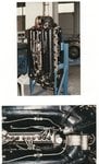
After reading technical documents and the book of Kyrill Von Gersdorff "Flugmotoren und Strahltribwerke", it appears that this CR was used to correct the small drop in manifold pressure in the R cylinder block owing to the design of the induction manifold. (See personal photos; the induction manifold connecting the R cylinder block is longer, so drop in manifold pressure for the R block and so increase in CR to correct it).
Don't forget! German engineers worked to improve the performances of the DB 601 E with minor modifications!
(Increase of RPM, altered valve timing to increase volumetric efficiency, increasing bore with existing cylinder center, repositioning of the sparks plugs and... different CR between the two blocks)
Best regards
Eric
This modification was introduced in DB 603 and in the next models.
After reading technical documents and the book of Kyrill Von Gersdorff "Flugmotoren und Strahltribwerke", it appears that this CR was used to correct the small drop in manifold pressure in the R cylinder block owing to the design of the induction manifold. (See personal photos; the induction manifold connecting the R cylinder block is longer, so drop in manifold pressure for the R block and so increase in CR to correct it).
Don't forget! German engineers worked to improve the performances of the DB 601 E with minor modifications!
(Increase of RPM, altered valve timing to increase volumetric efficiency, increasing bore with existing cylinder center, repositioning of the sparks plugs and... different CR between the two blocks)
Best regards
Eric
Attachments
jerryw
Airman 1st Class
The explanation in the von Gersdorff book is, like many given on this forum, is just guess work and it is WRONG. How could there possibly be "a small drop in manifold pressure on the right side, etc" if the two halves of the manifold were JOINED at the front!
The compression ratios for the cylinder banks on the DB601 engines were the same because the engine had gone into production before the problem was recognized.
The compression ratios for the cylinder banks on the DB601 engines were the same because the engine had gone into production before the problem was recognized.
jerryw
Airman 1st Class
If you thought the induction piping of the DB 601 was a bit lop-sided, have a look at this sketch of the intake tubes for the Junkers 211A (from Flight, 1940).
Entry to the "I" section is distinctly offset and the cylinder head common rails receive their feeds from very odd entrances.
Entry to the "I" section is distinctly offset and the cylinder head common rails receive their feeds from very odd entrances.
Attachments
kool kitty89
Senior Master Sergeant
Was the supercharger always on the port side (left when viewed from behind) of the Jumo? I seem to rember seeing intakes on the starboard side for the 211.
Edit: Nevermind, It's inverted... :embarassed: Thus that diagram is of the bottom of the engine. Pics like this don't help either:

Edit: Nevermind, It's inverted... :embarassed: Thus that diagram is of the bottom of the engine. Pics like this don't help either:
gareth pimm
Recruit
- 1
- Jan 4, 2009
i am trying to draw a 605 conrod
machined drawing from the engine anybody got such a drawing? the date 1943
machined drawing from the engine anybody got such a drawing? the date 1943
Johnny .45
Airman
This isn't about DB engines in particular, or even warbird engines, per se, but this whole topic is very interesting to me. I came to this page looking for evidence to show to someone who was very authoritatively explaining to everyone that the DB-series engines had no piston rings(!), because the tolerances were so tight(!!). I of course told him that was ridiculous. Anyway, this is the first I've head of the different compression ratios between the two banks of the DB605...sounds to me that the consensus is that it's either A.) the induction manifold or B.) a symptom of the oil system and cylinder leakage. My personal guess is that it's the oil system. Although it SOUNDS good, technically there's no reason that there should be any difference in the delivery pressures of the banks, unless there's a constriction in the ducting that speeds the air up. Or, unless the extra piping allows the starboard charge-air to cool down a slight bit more before it reaches the manifold....hmm, this IS a tricky one, huh? It doesn't seem like there's enough length to make a difference, which also says "oil system" to me. We're probably ALL wrong! LOL.
BUT the real reason I am posting is not to add my own guess. I've noticed on several occasions that the exhaust from two different cylinder banks on a vee-engine will be different, like one's blowing whiter smoke than the other. It's not always from the same bank; it can switch back and forth sometimes, but other times it's JUST the left or right bank. Could that be from a similar oil-seepage to the one you're talking about? Even on a non-inverted vee? And does it affect octane ratings enough to worry about in anything less than full-power? I am an engine fanatic, and this is just going to keep me thinking all day, both the DB induction/compression ratio thing AND the smoky cylinder banl issue. LOL, if I think of or find anything, I will let y'all know.
BUT the real reason I am posting is not to add my own guess. I've noticed on several occasions that the exhaust from two different cylinder banks on a vee-engine will be different, like one's blowing whiter smoke than the other. It's not always from the same bank; it can switch back and forth sometimes, but other times it's JUST the left or right bank. Could that be from a similar oil-seepage to the one you're talking about? Even on a non-inverted vee? And does it affect octane ratings enough to worry about in anything less than full-power? I am an engine fanatic, and this is just going to keep me thinking all day, both the DB induction/compression ratio thing AND the smoky cylinder banl issue. LOL, if I think of or find anything, I will let y'all know.
Danielp, you have just about answered your own question! The reason for the different compression ratios in the left and right cylinder banks was due to the difficulty experienced by DB in controlling the oil consumption in the inverted V-12 engine.
In the DB 601/5, the crankshaft spins anti-clockwise (as seen from the rear) and due to the windage, shape of the engine and gravity, more oil gets sprayed into the LHS bank compared to the RHS. (Remember, these engines had three-row roller bearings in the con-rod big-ends which allowed more oil to pass than conventional shell bearings.)
This excess oil would get past the piston rings and into the combustion chambers. If too much oil gets mixed with the fuel it lowers the octane rating and causes detonation. Thus they had to lower the C.R. of the left hand bank cylinders. It was a very crude solution to the problem.
The different CR's had NOTHING to do with the side-mounted supercharger!!
Hi,
since planes tend to fly banked and even headover and cause plane lose oil anyway(lower oil level would reduce the problem) and cause this would mean they had to reduce the max theoretical possible presure, this dont seems to be logical to me.
Hohuns clarification sounds logically. With this "trick" they was able to increase the engine power a little, without to do anything else. On motorbike engines even a little different air intakes make a different, same like different exhausts per cylinder.
Greetings,
Knegel
you don't really get a lot of windage inside a dry sumped motor that never sees 7000rpm
and blown motors don't have much issues with minor disparities in the manifolding, you don't have to tune the runners or finish the machining and it doesn't make any difference. The supercharger exhaust is close enough to the centre of the manifolding in the photos clearly, so that this wouldn't be the problem (maybe if it fed fully into one side of the manifold and then a cross pipe went to the other...but that's not the case).
problem is likely uneven heating between the banks. In this explanation you would notice it more with the higher operating speeds and larger cylinder displacement compared to the early 601.
in asking what else is different, the changed valve timing also means a lower dynamic compression which had to be compensated (although larger cylinder bores can usually handle more static compression on the same fuel grade to begin with), so I guess there might be an argument for cylinder leakage in terms of crankcase pressure giving variance between the banks (because of the roller bearings), but not an oil problem in the way described, pressure leakage of which a little oil in one bank would be a tell, but if it was enough to lower octane you'd be talking pouring oil through the cylinders by the litre. Pressure leakage, not oil lowering fuel octane.
I'd say one of those two or a combination of both off hand, at a guess.
jerryw
Airman 1st Class
There is a report that confirms that the different Compression Ratios on the DB V-12 engines was due to problems with OIL CONSUMPTION.
The Report is entitled, "Comments on Visit to Germany, July 24th 1945 to August 12th 1945'.
10 persons made up the visiting party, including P.G.Barlow and E. Wolsey (M.A.P.), Mr A. Thomas (Armstrong Siddeley Motors), Mr N. Quinn (Bristol Aero Co.), Mr R. Chamberlin (D. Napier Son) and Mr G. Morris ( Rolls-Royce Ltd).
Page 3 of the Report says, "A good example of Air Ministry control lies in the inverted Daimler-Benz engine. The D.B. people said that both from a technical and production point of view they would have preferred to make an upright engine but they were compelled to make it inverted by the Air Ministry.
With the inverted engine, they said it was very difficult to obtain consistent oil consumptions and due to the rotation of the crankshaft, one bank gets more oil than the other. For this reason the engine is built with a lower compression ratio on one bank than the other."
I think this is fairly conclusive documentary evidence on this matter.
Users who are viewing this thread
Total: 1 (members: 0, guests: 1)